CHAPTER 9: THEORY OF OPERATION DISTANCE ELEMENTS
D30 LINE DISTANCE PROTECTION SYSTEM – INSTRUCTION MANUAL 9-7
9
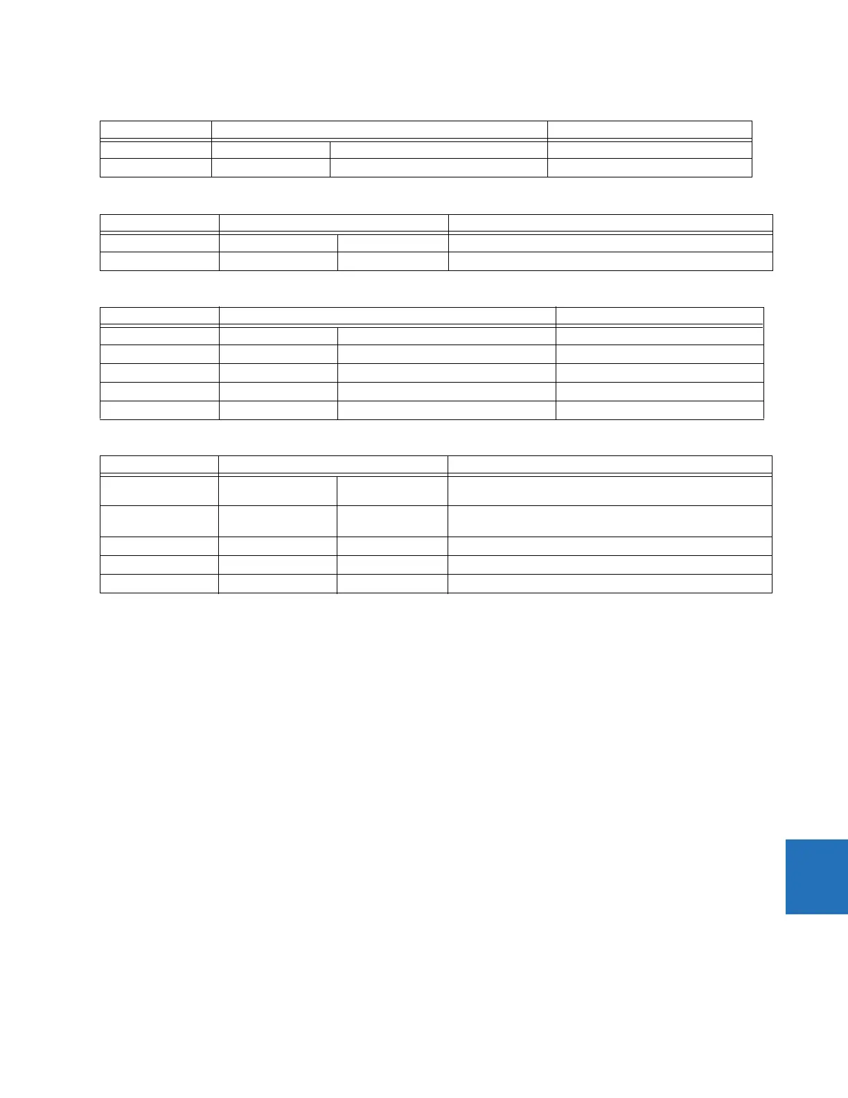
Table 9-5: Non-directional mho phase distance functions
Table 9-6: Non-directional mho ground distance functions
Table 9-7: Non-directional quadrilateral phase distance functions
Table 9-8: Non-directional quadrilateral ground distance functions
9.1.4 Fast distance algorithm
In order to improve operating speed of the phase and ground distance zone 1 and zone 2 elements under CVT transient
conditions for high SIRs up to 60, a fast distance algorithm is implemented in the relay. This algorithm uses a weighted
average digital filtering technique and runs in parallel with a regular distance algorithm, which uses a fixed digital CVT
filtering technique. The fast distance algorithm applies the same comparators as a regular distance algorithm.
The fast distance algorithm is activated upon detection of the system disturbance and is active for three cycles only. The
pickup and operate operands of the fast distance elements are internally OR-ed with regular distance elements, to achieve
integrated distance element optimal operating speed.
Note that fast distance is not active for the following applications:
• Use of the dynamic reach control for series-compensated line applications by selecting a non-zero value for the
voltage level setting in the Distance elements
• Non-directional option for the zone 1 and 2 Direction setting
• Phase Distance applications through power transformers, when the XFMR VOL CONNECTION or XFMR CUR
CONNECTION setting is other than "None"
9.1.5 Memory polarization
All distance functions use memory polarization. The positive-sequence voltage, either memorized or actual, is used as a
polarizing signal. The memory is established when the positive-sequence voltage remains above 80% of its nominal value
for five power system cycles. The memory voltage is a two-cycle old voltage.
Characteristic Comparator inputs Limit angle
Offset mho I × Z – V V-I × Z
REV
COMP LIMIT
Fault type NOT SLG See the Fault Type Characteristic section Removed during open pole conditions
Characteristic Comparator inputs Limit angle
Offset mho I × Z – V V-I × Z
REV
COMP LIMIT
Fault-type I_0 I_2 50°
Characteristic Comparator inputs Limit angle
Forward Reactance I × Z – V I × ZCOMP LIMIT
Reverse Reactance I × Z
REV
– V I × Z
REV
COMP LIMIT
Right Blinder I × Z
R
– V I × Z
R
90°
Left Blinder I × Z
L
– V I × Z
L
90°
Fault type NOT SLG See the Fault Type Characteristic section Removed during open pole conditions
Characteristic Comparator inputs Limit angle
Forward Reactance I × Z – V j × I_0 × e
jΘ
or j × I_2
× e
jΘ
COMP LIMIT
Reverse Reactance I × Z
REV
– V –j × I_0 × e
jΘ
or –j ×
I_2 × e
jΘ
COMP LIMIT
Right Blinder I × Z
R
– V I × Z
R
90°
Left Blinder I × Z
L
– V I × Z
L
90°
Fault-type I_0 I_2 50°
 Loading...


