3-30 D30 LINE DISTANCE PROTECTION SYSTEM – INSTRUCTION MANUAL
WIRING CHAPTER 3: INSTALLATION
3
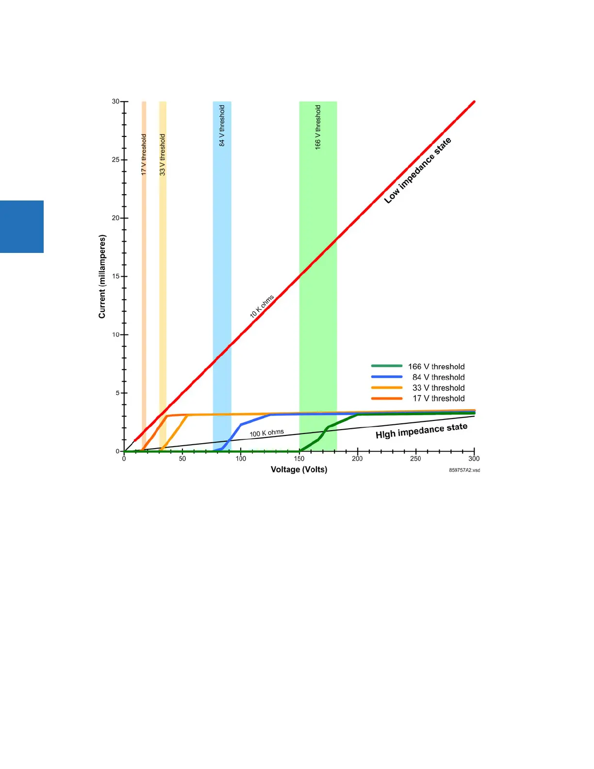
Figure 3-27: Active impedance contact input V-I characteristic
3.3.7 Transducer inputs and outputs
Transducer input modules receive input signals from external DCmA output transducers (DCmA In) or resistance
temperature detectors (RTDs). Hardware and software are provided to receive signals from these external transducers and
convert these signals into a digital format for use as required.
Transducer output modules provide DC current outputs in several standard DCmA ranges. Software is provided to
configure virtually any analog quantity used in the relay to drive the analog outputs.
Each transducer input/output module has 24 terminal connections. These connections are arranged as three terminals
per row over eight rows. A given row can be used for either inputs or outputs, with terminals in column "a" having positive
polarity and terminals in column "c" having negative polarity. Since an entire row is used for a single input/output channel,
the name of the channel is assigned using the module slot position and row number.
Each module also requires that a connection from an external ground bus be made to terminal 8b. The current outputs
require a twisted-pair shielded cable, where the shield is grounded at one end only. The following figure illustrates the
transducer module types (5A, 5C, 5D, 5E, and 5F) and channel arrangements that can be ordered for the relay.
 Loading...


