CHAPTER 9: THEORY OF OPERATION PHASE DISTANCE APPLIED TO POWER TRANSFORMERS
D30 LINE DISTANCE PROTECTION SYSTEM – INSTRUCTION MANUAL 9-15
9
Equations from the “Current Transformation” and “Voltage Transformation” columns are used to derive inputs to the three
(AB, BC, and CA) phase distance elements. For example, if the CTs are located at the delta side of the Delta-Wye 11
transformer, and a given zone is set to look through the transformer into the system connected to the Wye winding, the CT
location setting for that zone is set to Dy11 and the relay uses instead of a traditional I
A
- I
B
for the AB phase
distance element.
The current supervision pickup setting applies to the currents specified in the “Current Transformation” columns.
A distance zone originates at the location of the VTs (regardless of the location of the CTs). For information on settings see
the Application of Settings chapter.
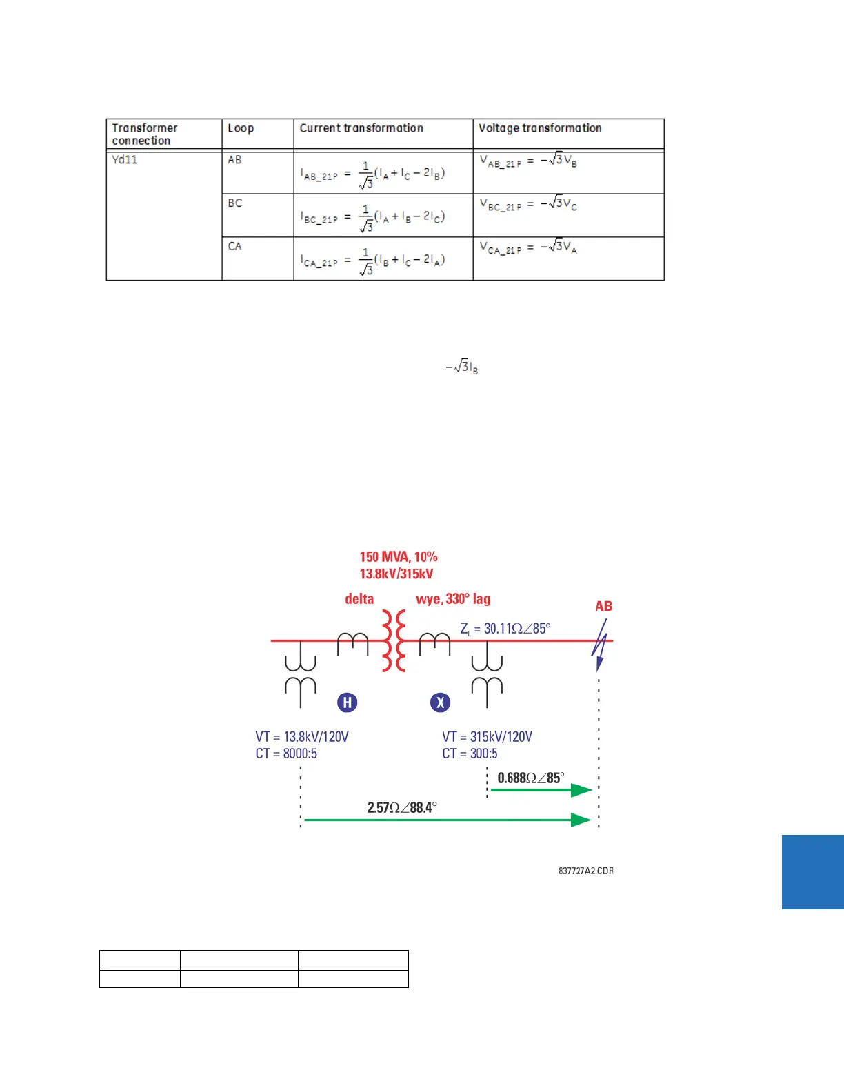
9.2.2 Example
Consider the system shown.
Figure 9-5: Sample system configuration
Normally, in order to respond to the fault shown in the figure, a distance relay is applied at the relaying point X. The table
outlines the relay input signals at this location.
Table 9-10: Relay input signals at location X
Input Primary Secondary
VA 100.4 kV ∠–7.32° 38.25 V ∠–7.32°
 Loading...


