CHAPTER 3: INSTALLATION PILOT CHANNEL COMMUNICATIONS
L90 LINE CURRENT DIFFERENTIAL SYSTEM – INSTRUCTION MANUAL 3-33
3
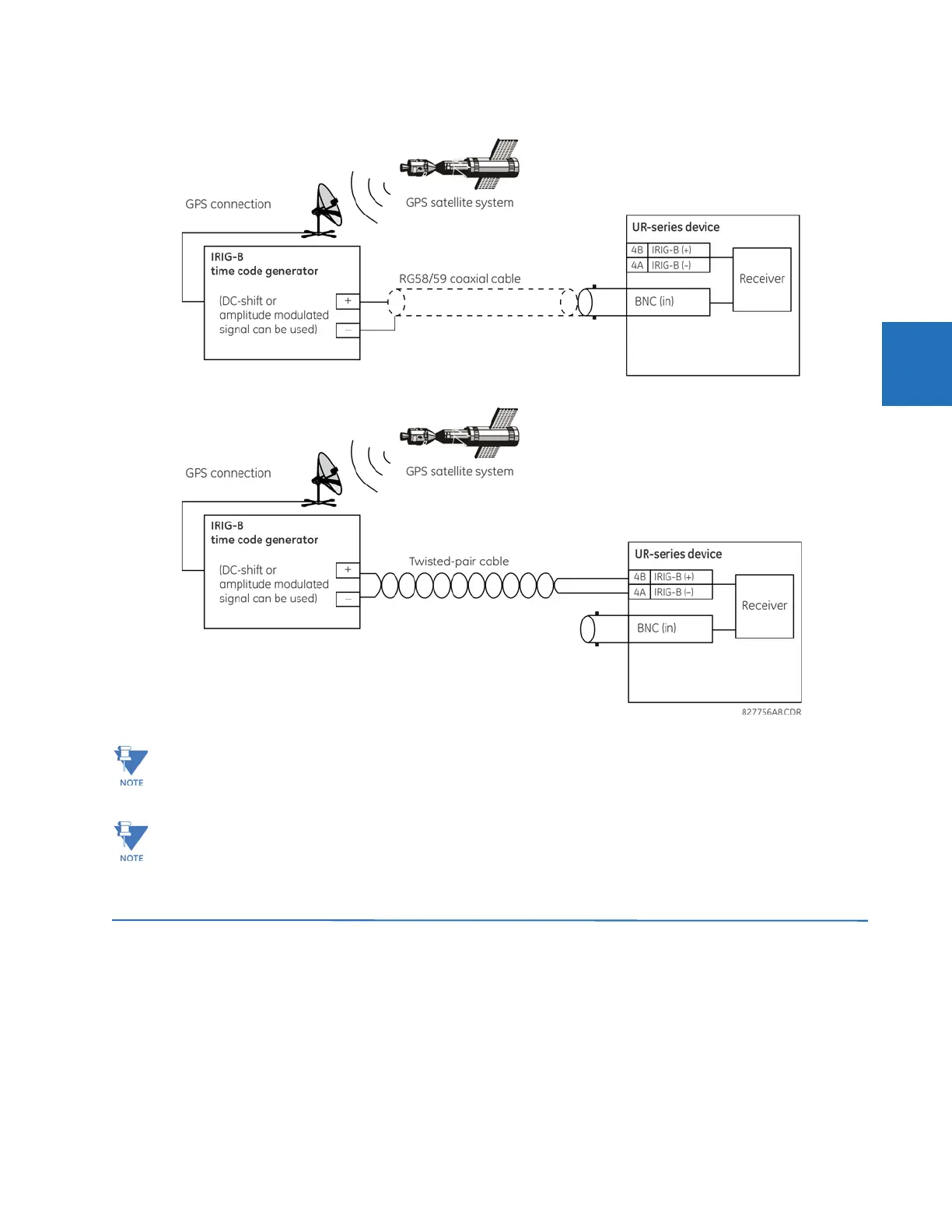
Figure 3-30: Options for the IRIG-B connection
3.4 Pilot channel communications
A special inter-relay communications module is available for the L90. This module is plugged into slot “W” in horizontally
mounted units and slot “R” in vertically mounted units. Inter-relay channel communications is not the same as 10/
100Base-F interface communications (available as an option with the CPU module). Channel communication is used for
sharing data among relays.
The inter-relay communications modules are available with several interfaces and some are outlined here in more detail.
Those that apply depend on options purchased. The options are outlined in the Inter-Relay Communications section of the
Order Code tables in Chapter 2.
Using an amplitude-modulated receiver causes errors up to 1 ms in event time stamping.
When IRIG-B is used as the time synchronization source for synchrophasors, the DC level shifted option must be
used in order to achieve the 1% Total Vector Error specified by the standard. If amplitude modulated IRIG-B is used,
it results in a 20 to 25 degree error in the synchrophasor angle measurement. The IEEE 1588 Precision Time
Protocol can also be used to achieve accurate time synchronization for synchrophasor calculation.
 Loading...


