8-26 L90 LINE CURRENT DIFFERENTIAL SYSTEM – INSTRUCTION MANUAL
PHASE DISTANCE THROUGH POWER TRANSFORMERS CHAPTER 8: APPLICATION OF SETTINGS
8
8.9 Phase distance through power transformers
8.9.1 Phase distance protection
8.9.1.1 Overview
Phase distance elements of the L90 can be set to respond to faults beyond any three-phase power transformer. The relay
guarantees accurate reach and targeting for any phase fault. Moreover, the current and voltage transformers can be
located independently on different sides of the transformer.
The following setting rules apply to this feature:
• A given distance zone is terminated by location of the VTs, not the CTs
• Consequently, the positive-sequence impedance of a transformer must be included in the reach setting only if the
transformer is located between the potential source and the intended reach point
• The current signals require compensation if the transformer is located between the CTs and the intended reach point.
If this is the case, set the CT connection setting to transformer connection and vector group as seen from the CTs
toward the reach point. Otherwise, set the CT connection setting to "None."
• The voltage signals require compensation if the transformer is located between the VTs and the intended reach point.
If this is the case, set the VT connection setting to transformer connection and vector group as seen from the VTs
toward the reach point. Otherwise, set the VT connection setting to "None."
• The reach setting is entered in secondary ohms and as such must take into account location and ratios of VTs and CTs,
as well as voltage ratio of the involved power transformer
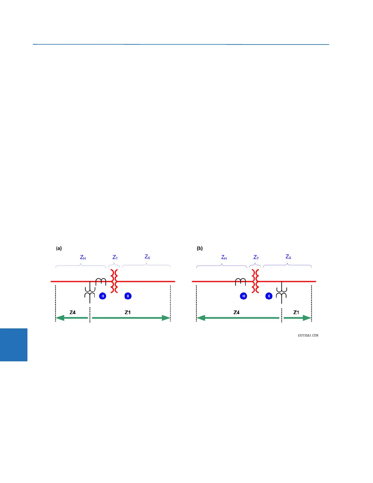
The following equations explain the setting rules. Consider two applications as shown in the figure.
Figure 8-9: Phase distance through a power transformer
where
Z
X
= intended reach impedance for Zone 1 (primary ohms)
Z
H
= intended reach impedance for Zone 4 (primary ohms)
Z
T
= positive-sequence impedance of the transformer
V
X
, V
H
= transformer rated voltages
n
CT
= transformation ratio of the CTs
n
VT
= transformation ratio of the VTs
Z1: Z1 reach setting (secondary ohms)
Z4: Zone 4 reach setting (secondary ohms)
 Loading...


