4-78 L90 LINE CURRENT DIFFERENTIAL SYSTEM – INSTRUCTION MANUAL
FLEXLOGIC DESIGN USING ENGINEER CHAPTER 4: INTERFACES
4
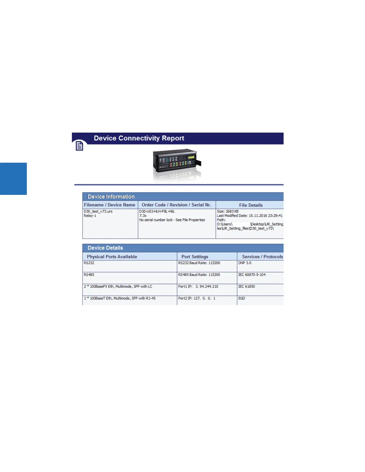
4.4.5 Generate connectivity report
This report displays basic information about a device, such as order code, port numbers, inputs and outputs. You can use it
to create a PDF file of basic information. The report is based on CID and/or IID files, and not the system or full SCD. All
device details including Remote Inputs, Remote Outputs, and Analog Inputs/Outputs are indicated, including quantities
used and available.
To display a device report:
1. In the Offline Window area of the software, expand the Engineer entry for the device.
2. Double-click the Device Connectivity Report entry. The report displays.
3. To save as a PDF file, click File > Save As.
Figure 4-88: Device Connectivity Report
4.4.6 Preferences
Preferences determine functionality. As such, you are encouraged to review them. This section outlines some options
available in the menus and preference panels.
Access them in the Logic Designer panel under the View menu and under File > Preferences. The Logic Designer and
Logic Monitor preferences are outlined here, not all preferences for a device.
4.4.6.1 View menu
View > Toolbar > Advanced Actions — Active when in Logic Designer. Toggles a toolbar to nudge, rotate, flip, or change
the order of an element.
View > Show Unused Pins — Enable to display unconnected pins. Disable to eliminate unconnected pins from the view, for
example when printing.
 Loading...


