3-50 L90 LINE CURRENT DIFFERENTIAL SYSTEM – INSTRUCTION MANUAL
INSTALL SOFTWARE CHAPTER 3: INSTALLATION
3
To activate the relay using EnerVista software:
1. Navigate to Settings > Product Setup > Installation and change the Relay Settings field to "Programmed."
2. Save the change.
3.6 Install software
3.6.1 EnerVista communication overview
The EnerVista UR Setup software communicates to the relay via the front panel RS232 port or the rear panel RS485 /
Ethernet ports.
To communicate via the RS232 port, use a standard straight-through serial cable. Connect the DB-9 male end to the relay
and the DB-9 or DB-25 female end to the computer COM2 port as described in the CPU Communication Ports section
earlier in this chapter.
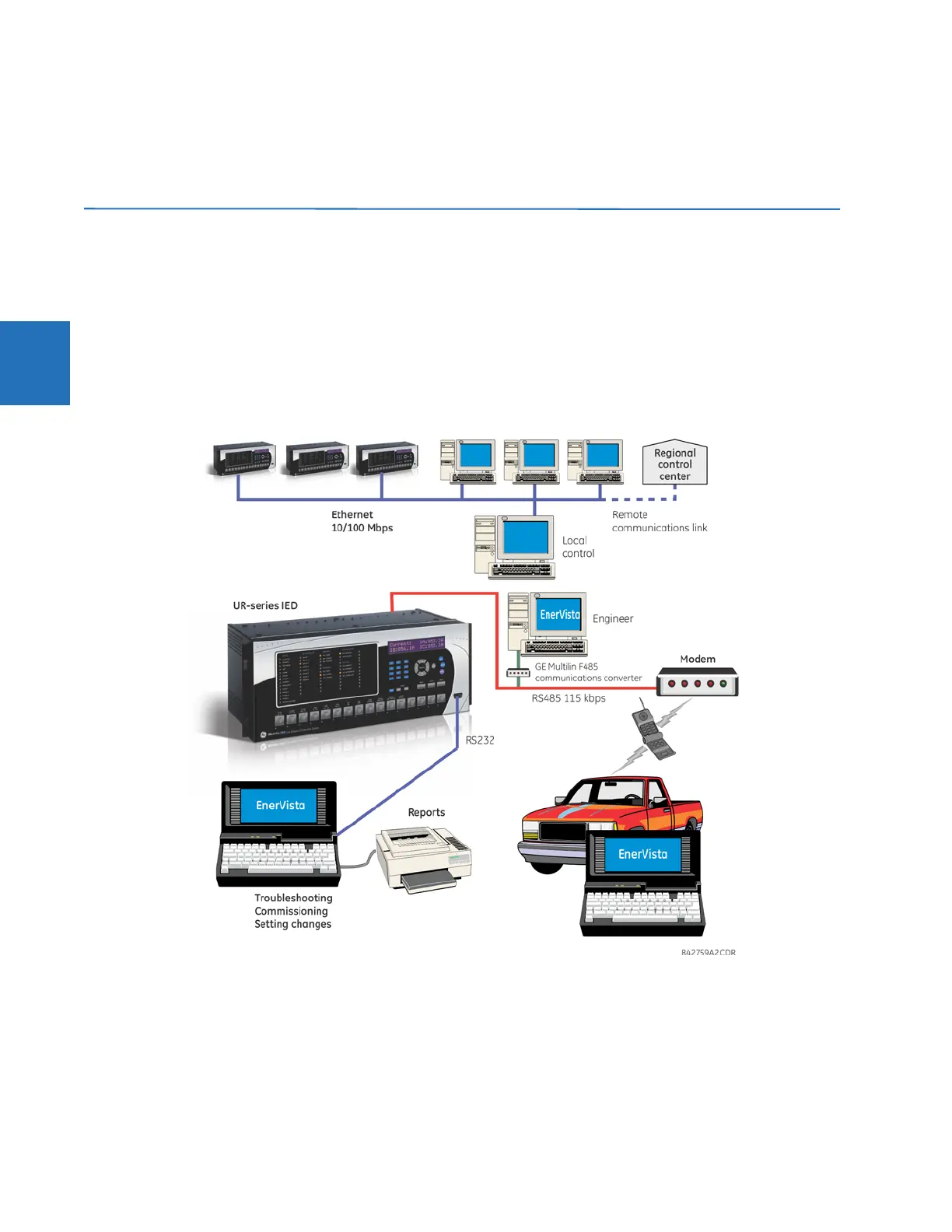
Figure 3-55: Relay communication options
To communicate through the L90 rear RS485 port from a computer RS232 port, the GE Grid Solutions RS232/RS485
converter box is required. This device (catalog number F485) connects to the computer using a straight-through serial
cable. A shielded twisted-pair (20, 22, or 24 AWG) connects the F485 converter to the L90 rear communications port. The
converter terminals (+, –, GND) are connected to the L90 communication module (+, –, COM) terminals. See the CPU
Communication Ports section in chapter 3 for details. The line is terminated with an R-C network (that is, 120 Ω, 1 nF) as
described in this chapter.
 Loading...


