6-30 L90 LINE CURRENT DIFFERENTIAL SYSTEM – INSTRUCTION MANUAL
RECORDS CHAPTER 6: ACTUAL VALUES
6
where
R
F
is the fault resistance in secondary ohms
Z
1
is the line positive-sequence impedance
D
pu
is the distance to fault in per unit
When the single-ended fault location method is applied, the fault loop impedance is calculated as per the following
equation.
Z
loop
= V
loop
/ I
loop
Eq. 6-9
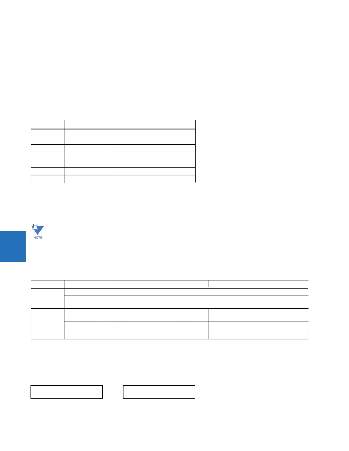
The table defines the loop voltage and current.
Table 6-3: Quantities used to calculate fault loop impedances
Where VA, VB, VC are phase voltage phasors in secondary volts; IA, IB, IC are current phasors in secondary amps, I0 is the
zero sequence current phasors in secondary amps; and IG is the ground current from the parallel line scaled to the source
phase CT in secondary amps. Z0/Z1 is the zero sequence impedance to positive sequence impedance ratio, and Z0M/Z1 is
mutual zero sequence impedance to positive sequence impedance ratio.
Depending on the number of terminals and the location method applied, the fault resistance and loop impedance are
reported in the different ways as tabulated in the following table.
Table 6-4: Report mechanism for fault resistance and loop impedance
6.5.2 Event records
6.5.2.1 Enhanced and standard front panels
ACTUAL VALUES RECORDS EVENT RECORDS
Fault type V
loop
I
loop
AG VA IA + (Z0/Z1-1)*I0 + Z0M/Z1*IG/3
BG VB IB + (Z0/Z1-1)*I0 + Z0M/Z1*IG/3
CG VC IC + (Z0/Z1-1)*I0 + Z0M/Z1*IG/3
AB, ABG VA – VB IA - IB
BC, BCG VB – VC IB - IC
CA, CAG VC – VA IC - IA
ABC Average of AB, BC, CA loop impedances
VTs of the FAULT REPORT 1 SOURCE must be connected in Wye or VT SUBSTITUTION must be set correctly for the Delta
connected VT to display the loop impedance and fault resistance for single phase-to-ground faults.
For the application of partially parallel circuits and in the case of single phase-to-ground faults, the reported fault
resistance and fault loop impedance may not be accurate even the compensation method is applied.
Method Number of terminals Fault resistance Loop impedance
Multi-ended 2 Report at two terminals, seen from the individual end
3 Only report at the line terminal of the faulted segment. At the other two terminals, results are
not applicable, set values to the maximum number 9999.99.
Single-ended 2 Not applicable, set to the maximum number
9999.99
Report at two terminals, seen from the
individual end
3 Not applicable, set to the maximum number
9999.99
Report at all terminals, but the value is only
accurate at the line terminal of the faulted
segment
EVENT RECORDS
EVENT: XXX
XXX
Date and time stamps
 Loading...


