CHAPTER 8: APPLICATION OF SETTINGS CURRENT DIFFERENTIAL (87L) SETTINGS
L90 LINE CURRENT DIFFERENTIAL SYSTEM – INSTRUCTION MANUAL 8-3
8
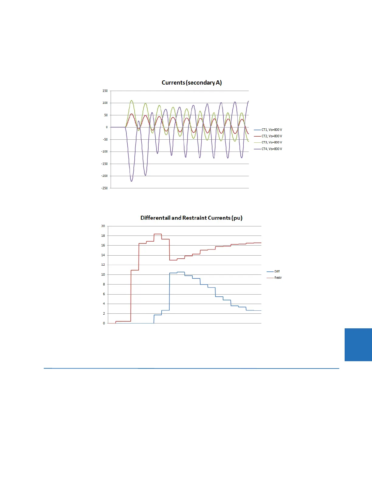
Once all data is entered, by clicking the Analyze button, you can observe differential and restraint currents through the
simulated fault in the Results tab, shown as follows. The application is considered secure when the worst through the plot
Irestr/Idiff > 1.25 with selected settings and all fault scenarios considered.
Figure 8-2: Tool results for currents
Figure 8-3: Tool results for differential and restraint currents
You are encouraged to test different fault locations and different fault levels and distributions per short circuit studies.
Alternatively, the tool can help to estimate required CT parameters (ratio and knee point voltage), based on some pre-
determined criteria.
8.2 Current differential (87L) settings
8.2.1 Introduction
Software is available from the GE Digital Energy website that is helpful in selecting settings for the specific application.
Checking the performance of selected element settings with respect to known power system fault parameters makes it
relatively simple to choose the optimum settings for the application.