CHAPTER 6: ACTUAL VALUES RECORDS
L90 LINE CURRENT DIFFERENTIAL SYSTEM – INSTRUCTION MANUAL 6-29
6
6.5 Records
6.5.1 Fault reports
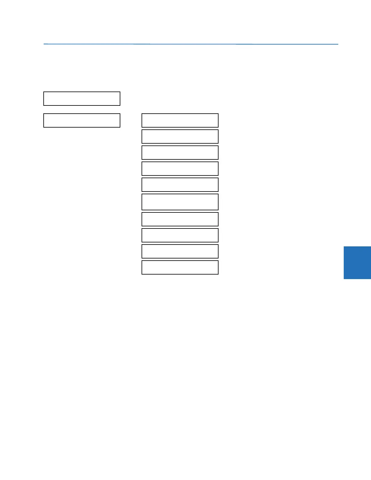
ACTUAL VALUES RECORDS FAULT REPORTS FAULT REPORT 1(15)
The latest 15 fault reports can be stored. The most recent fault location calculation (when applicable) is displayed in this
menu, along with the date and time stamp of the event which triggered the calculation. See the
SETTINGS PRODUCT
SETUP FAULT REPORTS
menu for assigning the source and trigger for fault calculations. See the COMMANDS CLEAR
RECORDS
menu for manual clearing of the fault reports and to the SETTINGS PRODUCT SETUP CLEAR RELAY RECORDS
menu for automated clearing of the fault reports.
The faulted segment of the line is indicated when the synchronized voltage and currents method is used. When the faulted
segment cannot be determined, the
FAULT 1 FAULTED SEGMENT value displays “N/A”. For three-terminal lines, the fault
location (distance to the fault) is reported as seen from the terminal adjacent to the fault. A FlexAnalog, Faulted Segment,
is linked to
FAULT 1 FAULTED SEGMENT, to indicate the faulted segment, where N/A is denoted as 0, Local as 1, Remote 1 as
2, and Remote 2 as 3. In the three-terminal application, if the fault is identified between the local terminal and the tap
point, the operand TAP-LOCAL FAULT is then asserted high at the local relay.
The
FAULT 1 FAULT RESIST displays the fault resistance at the fault point, which is shown in the secondary ohms. The
calculation is explained in the Theory of Operation chapter.
The
FAULT 1 LOOP RESISTANCE and REACTANCE are expressed in secondary ohms. When the multi-ended fault location
method is applied, the fault loop impedance is calculated as the summation of fault resistance and faulted portion of the
line positive sequence impedance. The fault loop resistance is calculated by
R
loop
= R
F
+ D
pu
x Real(Z
1
) Eq. 6-7
The fault loop reactance is calculated by
X
loop
= D
pu
x Imag(Z
1
) Eq. 6-8
NO FAULTS TO REPORT
or
FAULT REPORT 1
FAULT 1
LINE ID: SRC 1
Range: SRC 1, SRC 2, SRC 3, SRC 4
FAULT 1 DATE:
2000/08/11
Range: YYYY/MM/DD
FAULT 1 TIME:
00:00:00.000000
Range: HH:MM:SS.ssssss
FAULT 1 TYPE:
ABG
Range: not available if the source VTs are in the
“Delta” configuration
FAULT 1 LOCATION
00.0 km
Range: not available if the source VTs are in the
“Delta” configuration
FAULT 1 FAULTED
SEGMENT: Local
Range: N/A, Local (two-terminal configuration and local
section for three-terminal), Remote 1, Remote 2 (three-
terminal configuration only)
FAULT 1 RECLOSE
SHOT: 0
Range: where applicable
FAULT 1 LOOP
RESIST: 0.00 Ohms
Range: 0 to 327.67 Ohms
FAULT 1 LOOP
REACT: 0.00 Ohms
Range: -327.67 to 327.67 Ohms
FAULT 1 FAULT
RESIST: 0.00 Ohms
Range: 0 to 327.67 Ohms
 Loading...


