CHAPTER 4: INTERFACES FLEXLOGIC DESIGN USING ENGINEER
L90 LINE CURRENT DIFFERENTIAL SYSTEM – INSTRUCTION MANUAL 4-63
4
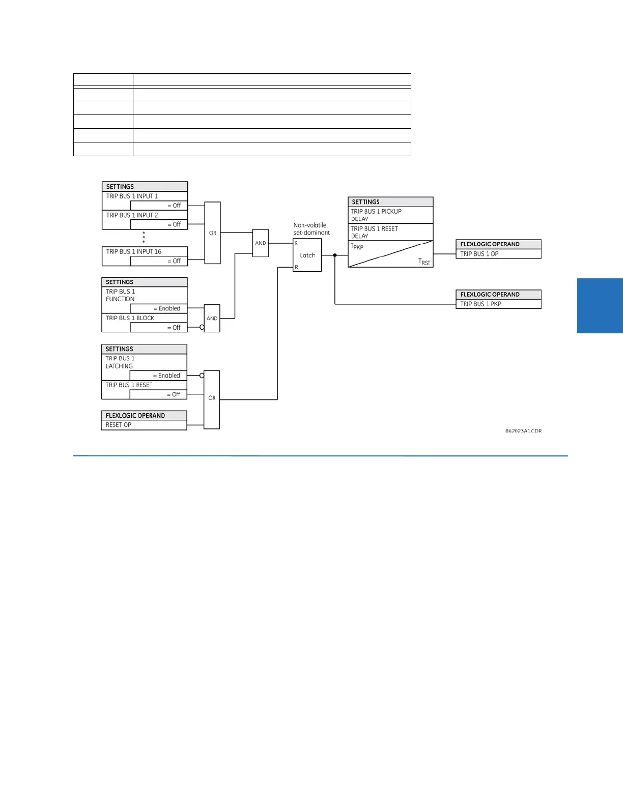
Figure 4-64: Logic diagram
4.4 FlexLogic design using Engineer
Parts of EnerVista Viewpoint Engineer software are integrated in the EnerVista UR Setup software. Engineer can be used to
create and modify FlexLogic that is used by a device, such as to monitor output, monitor triggers, and create self-tests.
Features include
• Automatically displays existing FlexLogic
• Drag-and-drop interface
• Open multiple tabs and edit simultaneously
• Display symbols in IEC, ISO, or UR formats
• Export a diagram as BMP file or copy it to the clipboard for import into other applications
• Scale and print files in various paper sizes
• Works with all UR firmware versions
The figure shows an example where several inputs are used to trigger an output. With the OR function, any one of the
inputs can trigger the output.
Not. Negates/reverses the output, for example 0 becomes 1.
Connection
S, R Set, Reset
T
PKP
Timer pickup. Triggered by the settings latch in the diagram.
T
RST
Timer reset. Triggered by the reset latch in the diagram.
Symbol Description
 Loading...


