CHAPTER 3: INSTALLATION PILOT CHANNEL COMMUNICATIONS
L90 LINE CURRENT DIFFERENTIAL SYSTEM – INSTRUCTION MANUAL 3-35
3
Figure 3-33: 2I and 2J laser fiber modules
3.4.3 G.703 interface
3.4.3.1 Description
The following figure shows the 64K ITU G.703 co-directional interface configuration.
The G.703 module is fixed at 64 kbps. The
SETTINGS PRODUCT SETUP DIRECT I/O DIRECT I/O DATA RATE setting is not
applicable to this module.
AWG 24 twisted shielded pair is recommended for external connections, with the shield grounded only at one end.
Connecting the shield to pin X1a or X6a grounds the shield since these pins are connected internally to ground. Thus, if
pin X1a or X6a is used to ground the shield at one end, do not ground the shield at the other end. This interface module is
protected by surge suppression devices.
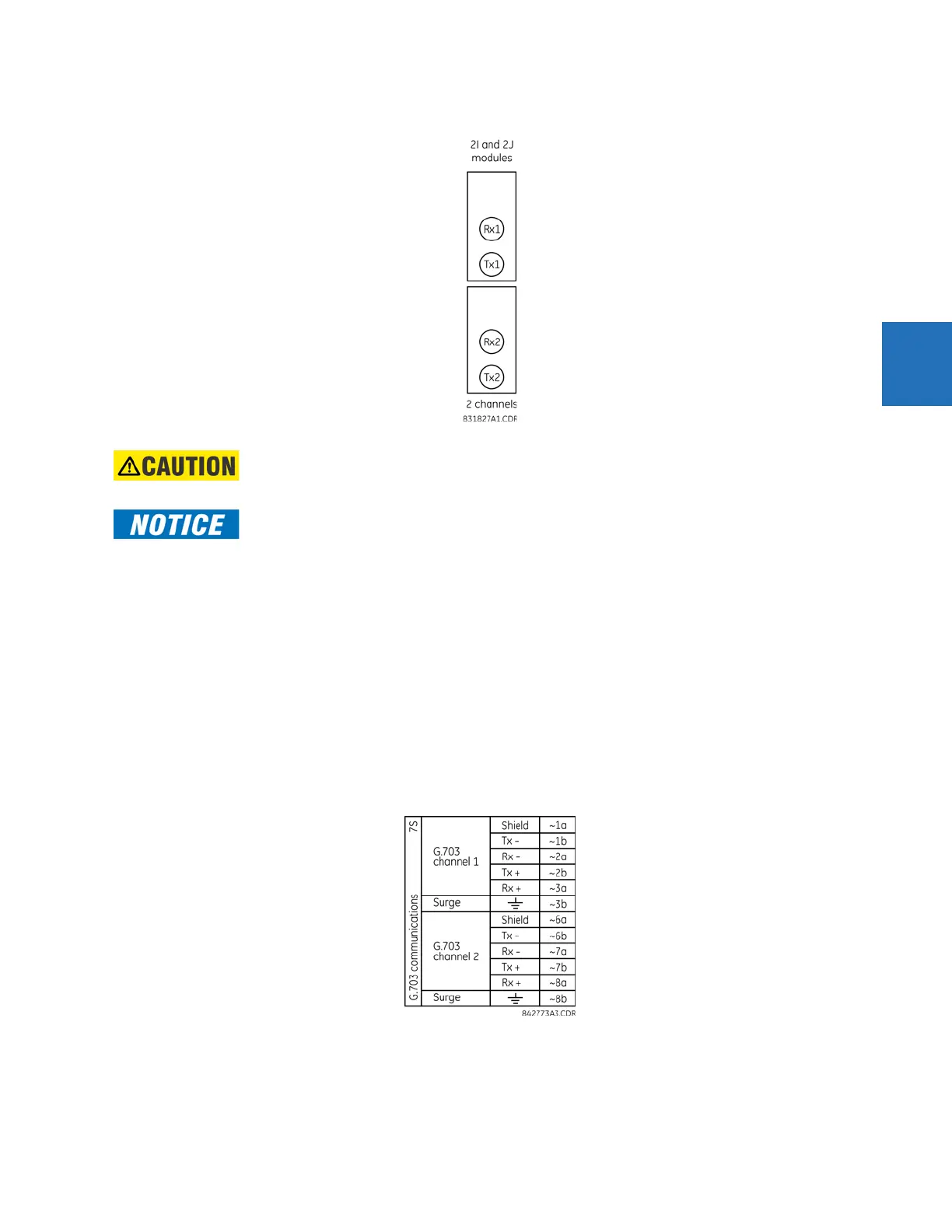
Figure 3-34: G.703 interface configuration
The following figure shows the typical pin interconnection between two G.703 interfaces. For the actual physical
arrangement of these pins, see the Rear Terminal Layout section earlier in this chapter. All pin interconnections are to be
maintained for a connection to a multiplexer.
Observing any fiber transmitter output can injure the eye.
When using a laser Interface, attenuators can be necessary to ensure that you do not exceed the
maximum optical input power to the receiver.
 Loading...


