10-26 L90 LINE CURRENT DIFFERENTIAL SYSTEM – INSTRUCTION MANUAL
DISTANCE ELEMENTS CHAPTER 10: THEORY OF OPERATION
10
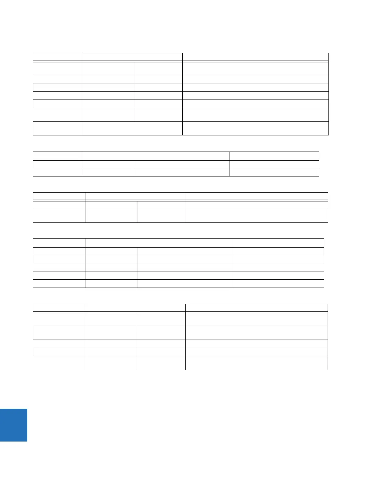
Table 10-4: Directional quadrilateral ground distance functions
Table 10-5: Non-directional mho phase distance functions
Table 10-6: Non-directional mho ground distance functions
Table 10-7: Non-directional quadrilateral phase distance functions
Table 10-8: Non-directional quadrilateral ground distance functions
10.3.4 Fast distance algorithm
In order to improve operating speed of the phase and ground distance zone 1 and zone 2 elements under CVT transient
conditions for high SIRs up to 60, a fast distance algorithm is implemented in the relay. This algorithm uses a weighted
average digital filtering technique and runs in parallel with a regular distance algorithm, which uses a fixed digital CVT
filtering technique. The fast distance algorithm applies the same comparators as a regular distance algorithm.
Characteristic Comparator inputs Limit angle
Reactance I × Z – V j × I_0 × e
jΘ
or j × I_2
× e
jΘ
COMP LIMIT
Directional I_0 × Z
D
V_1M DIR COMP LIMIT
Directional I_2 × Z
D
V_1M DIR COMP LIMIT (removed when 3I_0 > OC SUPV and I_2 < CUTOFF)
Right Blinder I × Z
R
– V I × Z
R
90°
Left Blinder I × Z
L
– V I × Z
L
90°
Fault-type I_0 I_2 50° (removed during open pole conditions or when 3I_0 > OC SUPV
and I_2 < CUTOFF)
Zero-sequence I_0 × Z
D
–V_0 90° (zones and higher only; removed for zones 2 and higher during
open pole conditions)
Characteristic Comparator inputs Limit angle
Offset mho I × Z – V V-I × Z
REV
COMP LIMIT
Fault type NOT SLG See the Fault Type Characteristic section Removed during open pole conditions
Characteristic Comparator inputs Limit angle
Offset mho I × Z – V V-I × Z
REV
COMP LIMIT
Fault-type I_0 I_2 50° (removed during open pole conditions or when 3I_0 > OC
SUPV and I_2 < CUTOFF)
Characteristic Comparator inputs Limit angle
Forward Reactance I × Z – V I × ZCOMP LIMIT
Reverse Reactance I × Z
REV
– V I × Z
REV
COMP LIMIT
Right Blinder I × Z
R
– V I × Z
R
90°
Left Blinder I × Z
L
– V I × Z
L
90°
Fault type NOT SLG See the Fault Type Characteristic section Removed during open pole conditions
Characteristic Comparator inputs Limit angle
Forward Reactance I × Z – V j × I_0 × e
jΘ
or j × I_2
× e
jΘ
COMP LIMIT
Reverse Reactance I × Z
REV
– V –j × I_0 × e
jΘ
or –j ×
I_2 × e
jΘ
COMP LIMIT
Right Blinder I × Z
R
– V I × Z
R
90°
Left Blinder I × Z
L
– V I × Z
L
90°
Fault-type I_0 I_2 50° (removed during open pole conditions or when 3I_0 > OC
SUPV and I_2 < CUTOFF)
 Loading...


