CHAPTER 5: SETTINGS GROUPED ELEMENTS
L90 LINE CURRENT DIFFERENTIAL SYSTEM – INSTRUCTION MANUAL 5-245
5
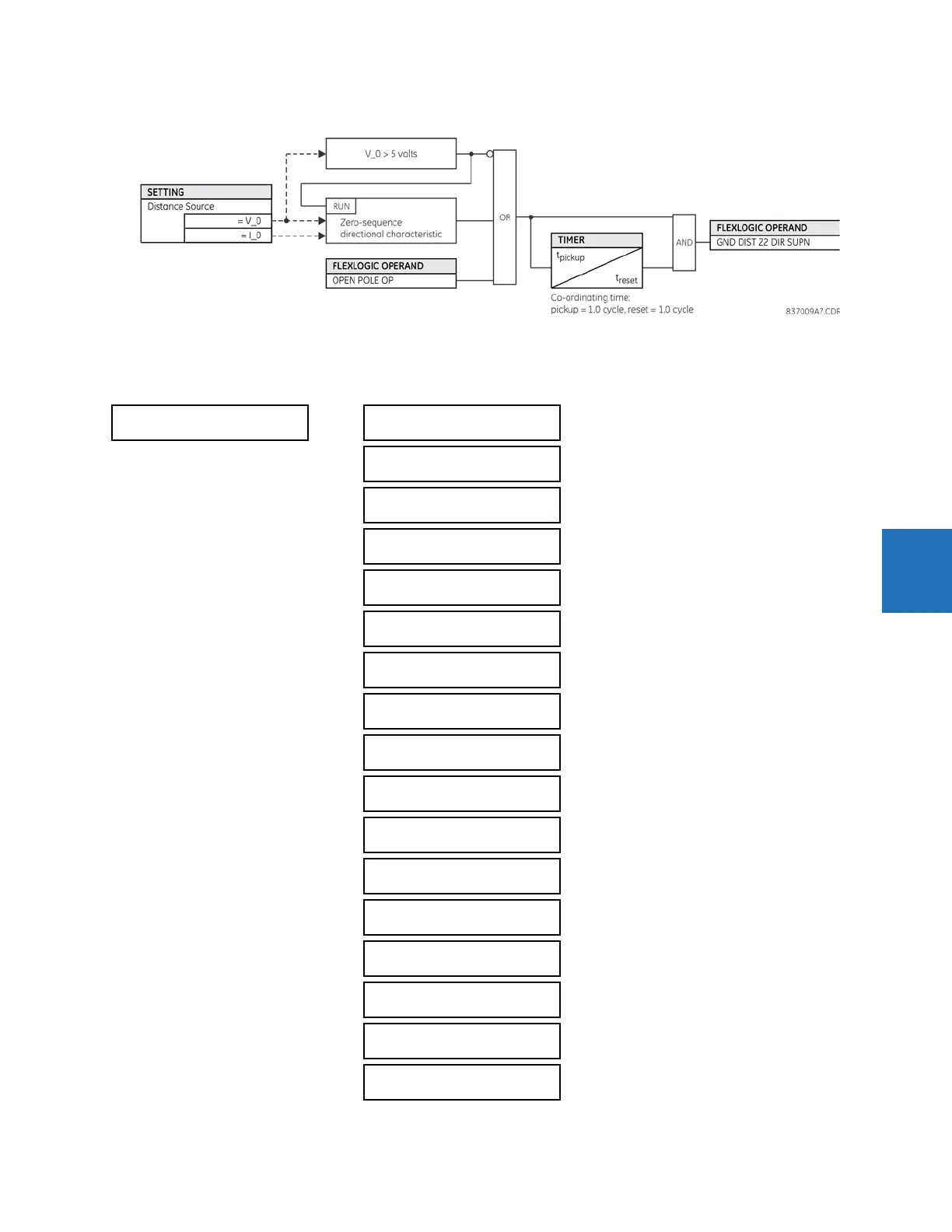
Figure 5-131: Ground directional supervision logic
5.7.6 Power swing detect (ANSI 68)
SETTINGS GROUPED ELEMENTS SETTING GROUP 1(6) POWER SWING DETECT
POWER SWING
DETECT
POWER SWING
FUNCTION: Disabled
Range: Disabled, Enabled
POWER SWING
SOURCE: SRC 1
Range: SRC 1, SRC 2, SRC 3, SRC 4
POWER SWING
SHAPE: Mho Shape
Range: Mho Shape, Quad Shape
POWER SWING
MODE: Two Step
Range: Two Step, Three Step
POWER SWING
SUPV: 0.600 pu
Range: 0.050 to 30.000 pu in steps of 0.001
POWER SW I2 SUPV ENAB:
Off
Range: FlexLogic operand
POWER SWING
I2 SUPV: 0.200 pu
Range: 0.050 to 30.000 pu in steps of 0.001
POWER SWING FWD
REACH: 50.00 Ω
Range: 0.10 to 500.00 ohms in steps of 0.01
POWER SWING QUAD FWD
REACH MID: 60.00 Ω
Range: 0.10 to 500.00 ohms in steps of 0.01
POWER SWING QUAD FWD
REACH OUT: 70.00 Ω
Range: 0.10 to 500.00 ohms in steps of 0.01
POWER SWING FWD
RCA: 75°
Range: 40 to 90° in steps of 1
POWER SWING REV
REACH: 50.00 Ω
Range: 0.10 to 500.00 ohms in steps of 0.01
POWER SWING QUAD REV
REACH MID: 60.00 Ω
Range: 0.10 to 500.00 ohms in steps of 0.01
POWER SWING QUAD REV
REACH OUT: 70.00 Ω
Range: 0.10 to 500.00 ohms in steps of 0.01
POWER SWING REV
RCA: 75°
Range: 40 to 90° in steps of 1
POWER SWING OUTER
LIMIT ANGLE: 120°
Range: 40 to 140° in steps of 1
POWER SWING MIDDLE
LIMIT ANGLE: 90°
Range: 40 to 140° in steps of 1
 Loading...


