CHAPTER 5: SETTINGS INPUTS/OUTPUTS
L90 LINE CURRENT DIFFERENTIAL SYSTEM – INSTRUCTION MANUAL 5-413
5
FREQ RATE 1 MAX FREQUENCY — This setting defines the maximum frequency level required for operation of the element.
The setting can be used to effectively block the feature based on frequency. For example, if the intent is to monitor a
decreasing trend but only if the frequency is already below a certain level (such as for load shedding), set this setting to the
required frequency level.
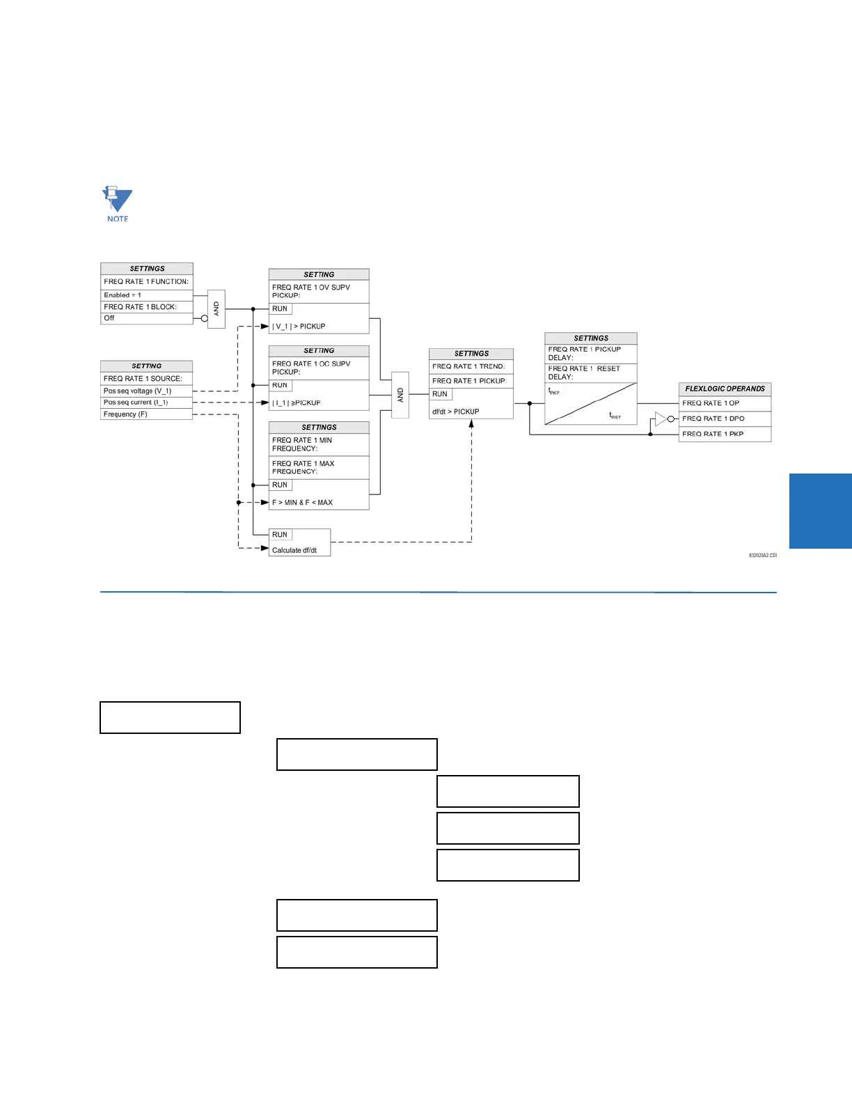
Figure 5-229: Frequency rate of change logic
5.9 Inputs/outputs
5.9.1 Contact inputs
SETTINGS INPUTS/OUTPUTS CONTACT INPUTS
If the signal source assigned to the frequency rate of change element is only set to auxiliary VT, then the minimum
voltage supervision is 3 V.
CONTACT INPUTS
CONTACT INPUT H5a
CONTACT INPUT H5a ID:
Cont Ip 1
Range: up to 20 alphanumeric
characters
CONTACT INPUT H5a
DEBNCE TIME: 6.0 ms
Range: 0.0 to 16.0 ms in steps of 0.5
CONTACT INPUT H5a
EVENTS: Disabled
Range: Disabled, Enabled
↓
CONTACT INPUT xxx
CONTACT INPUT
THRESHOLDS
 Loading...


