9-4 L90 LINE CURRENT DIFFERENTIAL SYSTEM – INSTRUCTION MANUAL
TESTING CHAPTER 9: COMMISSIONING
9
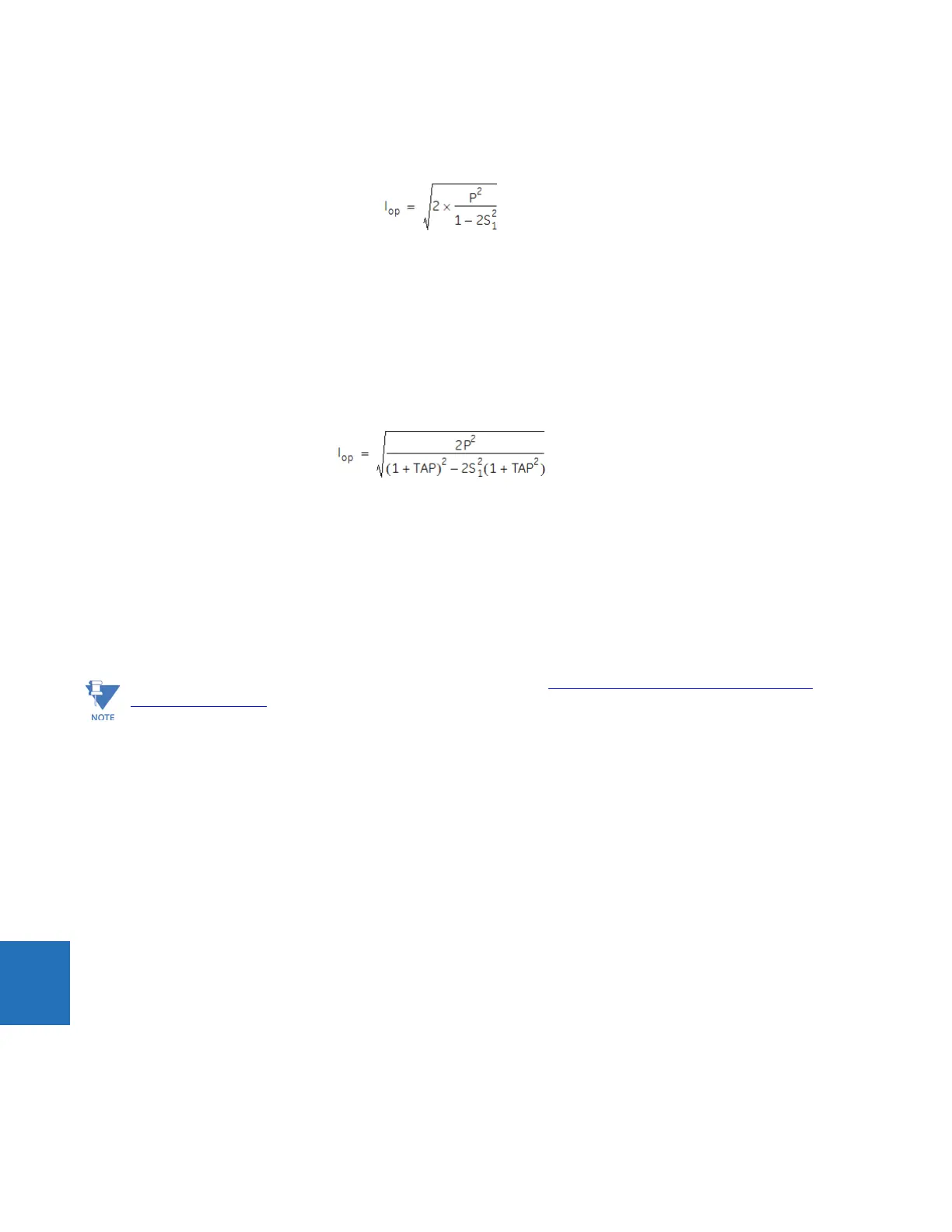
3.2. Slowly increase the current until the relay operates and note the pickup value. The theoretical value of
operating current below the breakpoint is given by the following formula, where P is the pickup setting and S
1
is
the Slope 1 setting (in decimal format):
Eq. 9-1
3.3. Repeat the above test for different slope and pickup settings, if desired.
3.4. Repeat the above tests for Phases B and C.
4. Minimum pickup test with local current and simulated remote current (pure internal fault simulation):
4.1. Disconnect the local relay from the communications channel.
4.2. Loop back the transmit signal to the receive input on the back of the relay.
4.3. Wait until the CHANNEL and PFLL status displays indicate OK.
4.4. Slowly increase the current until the relay operates and note the pickup value. The theoretical value of
operating current below breakpoint is given by the following formula:
Eq. 9-2
where
TAP represents the CT Tap setting for the corresponding channel
4.5. Repeat the above test for different slope and pickup settings, if desired.
4.6. During the tests, observe the current phasor at
ACTUAL VALUES METERING 87L DIFF CURRENT LOCAL IA.
This phasor should also be seen at
ACTUAL VALUES METERING 87L DIFF CURRENT TERMINAL 1(2) IA along
with a phasor of twice the magnitude at
ACTUAL VALUES METERING 87L DIFF CURRENT IA DIFF.
4.7. Repeat the above tests for Phases B and C.
4.8. Restore the communication circuits to normal.
9.1.4 Local-remote relay tests
9.1.4.1 Direct transfer trip (DTT) tests
The direct transfer trip is a function by which one relay sends a signal to a remote relay to cause a trip of remote
equipment. The local relay trip outputs closes upon receiving a direct transfer trip from the remote relay. The test
procedure is as follows:
1. Ensure that relay will not issue any undesired signals to other equipment and all previous tests have been completed
successfully.
2. Cycle power off/on in both relays.
3. Verify and record that both relays indicate In Service on the faceplate display.
4. Make the following setting change in the
SETTINGS GROUPED ELEMENTS LINE DIFFERENTIAL ELEMENT CURRENT
DIFFERENTIAL
menu of both relays:
CURRENT DIFF FUNCTION: “Enabled”
5. Verify and record that both relays have established communications by performing the following status check
thorough the
ACTUAL VALUES STATUS CHANNEL TESTS menu:
CHANNEL 1(2) STATUS: “OK”
Download the UR test software from the GE Grid Solutions website (http://www.gegridsolutions.com/products/
support/ur/l90test.zip) or contact GE Grid Solutions for information about the UR current differential test program
that allows the user to simulate different operating conditions for verifying correct responses of the relays during
commissioning activities.
 Loading...


