CHAPTER 5: SETTINGS SYSTEM SETUP
L90 LINE CURRENT DIFFERENTIAL SYSTEM – INSTRUCTION MANUAL 5-141
5
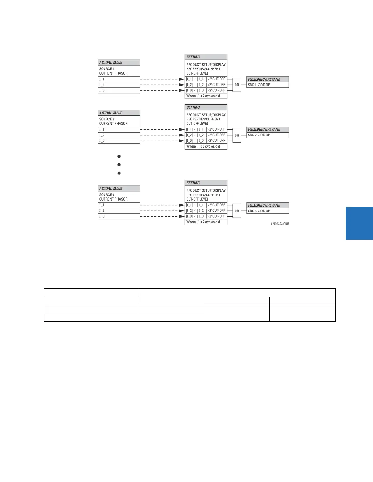
Figure 5-62: Disturbance detector logic
The disturbance detector responds to the change in currents of twice the current cut-off level. The default cut-off threshold
is 0.02 pu; thus by default the disturbance detector responds to a change of 0.04 pu. The metering sensitivity setting
(
PRODUCT SETUP DISPLAY PROPERTIES CURRENT CUT-OFF LEVEL) controls the sensitivity of the disturbance detector
accordingly.
5.5.3.4 Example for use of sources
An example of the use of sources is shown in the following figure. A relay can have the following hardware configuration:
This configuration can be used on a two-winding transformer, with one winding connected into a breaker-and-a-half
system. The following figure shows the arrangement of sources used to provide the functions required in this application,
and the CT/VT inputs that are used to provide the data.
Increasing slot position letter -->
UR CT/VT module 1 CT/VT module 2 CT/VT module 3
B30, B90, C70, F35, N60, T35 8 CTs 4 CTs, 4 VTs 4 CTs, 4 VTs
C60, D60, G30, G60, L30, L90, M60, T60 CTs VTs not applicable
 Loading...


