CHAPTER 5: SETTINGS SYSTEM SETUP
L90 LINE CURRENT DIFFERENTIAL SYSTEM – INSTRUCTION MANUAL 5-149
5
These settings ensure that the 87L element correctly applies magnitude and phase compensation for the in-zone
transformer. To accommodate for the difference in CT ratios at line terminals, use the
SETTINGS GROUPED ELEMENTS
SETTING GROUP 1(6) LINE DIFFERENTIAL ELEMENTS CURRENT DIFFERENTIAL CURRENT DIFF CT TAP
setting. It is important
to properly program the in-zone transformer setting for all terminals to ensure correct 87L performance.
IN-ZONE TRANSFORMER CONNECTION — This setting indicates the presence and group connection of the in-zone
transformer. The winding angle selection specifies the phase shift of the remote terminal side winding with respect to the
local terminal side winding. For example, for the Dy1 group where the delta winding is connected to the local terminal side,
and wye winding is connected to the remote terminal side, you select “30° lag” for the local terminal side. (At the remote
terminal relay, select “330° lag” for this transformer group connection.) If there is no in-zone transformer connected, then
program this setting as “None” (note that the “0° lag” value does not correspond to “None”). Only one in-zone transformer
is allowed for both two-terminal and three-terminal applications. Enabling in-zone transformer functionality forces the L90
to automatically remove the zero-sequence component from all terminals currents. It also disables ground differential
87LG functionality and zero-sequence current removal functionality defined by the
ZERO SEQ CURRENT REMOVAL setting.
Do not set the
IN-ZONE TRANSFORMER CONNECTION setting to "None" at one terminal and set other terminals to a value
other than "None." 87L is blocked under these circumstances.
TRANSFORMER LOCATION — This setting selects the transformer location and applies only when the IN-ZONE TRANSFORMER
CONNECTION
setting is other than “None.”
Select the “LOCAL-TAP” value if the transformer is present between the local terminal and the tap point or for two-terminal
applications.
Select “REM1-TAP” if the transformer is present between remote terminal 1 and the tap point.
Select “REM2-TAP” if the transformer is present between remote terminal 2 and the tap point.
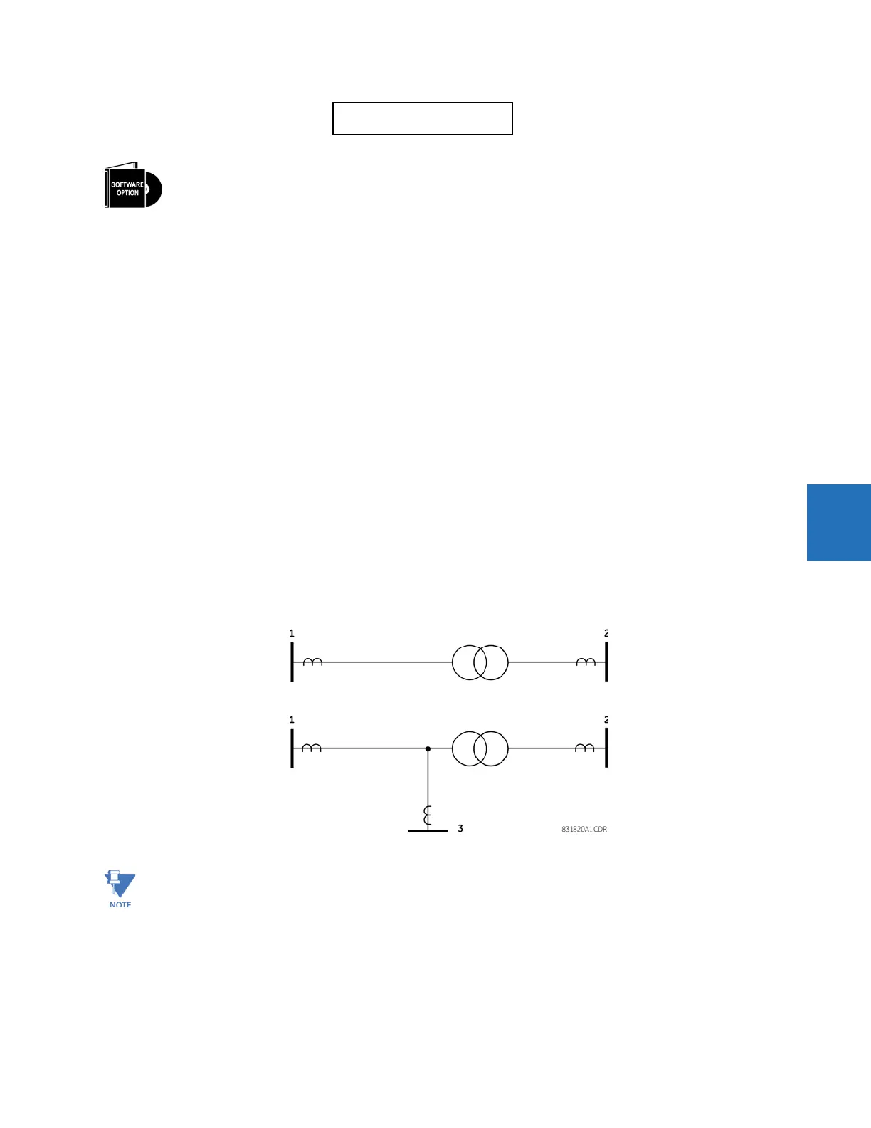
Figure 5-66: Illustration of in-zone transformer for two-terminal and three-terminal lines
TRANSFORMER LOCATION:
LOCAL-TAP
Range: LOCAL-TAP, REM1-TAP, REM2-TAP
The L90 is provided with this optional feature, specified as an option at the time of ordering. Using the order
code for your device, see the order codes in chapter 2 for details.
When the L90 ordered has in-zone functionality, it does not support the multi-ended fault locator.
 Loading...


