CHAPTER 5: SETTINGS GROUPED ELEMENTS
L90 LINE CURRENT DIFFERENTIAL SYSTEM – INSTRUCTION MANUAL 5-285
5
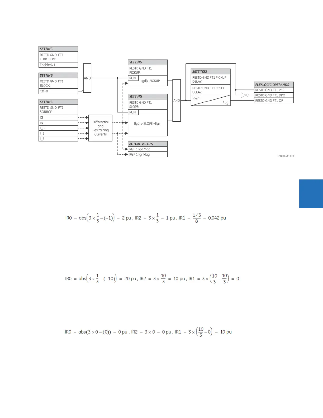
Figure 5-156: Restricted ground fault logic
The following examples explain how the restraining signal is created for maximum sensitivity and security. These examples
clarify the operating principle and provide guidance for testing of the element.
Example 1: External single-line-to-ground fault
Given the following inputs: IA = 1 pu ∠0°, IB = 0, IC = 0, and IG = 1 pu ∠180°
The relay calculates the following values:
Igd = 0, , and Igr = 2 pu
The restraining signal is twice the fault current. This gives extra margin if the phase or neutral CT saturates.
Example 2: External high-current SLG fault
Given the following inputs: IA = 10 pu ∠0°, IB = 0, IC = 0, and IG = 10 pu ∠–180°
The relay calculates the following values:
Igd = 0, , and Igr = 20 pu
Example 3: External high-current three-phase symmetrical fault
Given the following inputs: IA = 10 pu ∠0°, IB = 10 pu ∠–120°, IC = 10 pu ∠120°, and IG = 0 pu
The relay calculates the following values:
Igd = 0, , and Igr = 10 pu
Example 4: Internal low-current single-line-to-ground fault under full load
Given the following inputs: IA = 1.10 pu ∠0°, IB = 1.0 pu ∠–120°, IC = 1.0 pu ∠120°, and IG = 0.05 pu ∠0°
The relay calculates the following values:
I_0 = 0.033 pu ∠0°, I_2 = 0.033 pu ∠0°, and I_1 = 1.033 pu ∠0°
 Loading...


