5-288 L90 LINE CURRENT DIFFERENTIAL SYSTEM – INSTRUCTION MANUAL
GROUPED ELEMENTS CHAPTER 5: SETTINGS
5
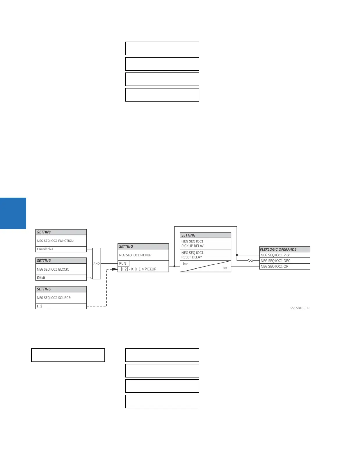
The negative-sequence instantaneous overcurrent element can be used as an instantaneous function with no intentional
delay or as a definite time function. The element responds to the negative-sequence current fundamental frequency
phasor magnitude (calculated from the phase currents) and applies a positive-sequence restraint for better performance:
a small portion (12.5%) of the positive-sequence current magnitude is subtracted from the negative-sequence current
magnitude when forming the operating quantity.
I
op
= |I_2| - K x |I_1| where K = 1/8 Eq. 5-34
The positive-sequence restraint allows for more sensitive settings by counterbalancing spurious negative-sequence
currents resulting from
• System unbalances under heavy load conditions
• Transformation errors of current transformers (CTs) during three-phase faults
• Fault inception and switch-off transients during three-phase faults
The positive-sequence restraint must be considered when testing for pickup accuracy and response time (multiple of
pickup). The operating quantity depends on how the test currents are injected into the relay (single-phase injection:
I
op
= 0.2917 x I
injected
; three-phase injection, opposite rotation: I
op
= I
injected
).
Figure 5-158: Negative sequence IOC1 logic
5.7.12.4 Negative sequence directional overcurrent (ANSI 67Q, IEC PDEF/PTOC)
SETTINGS GROUPED ELEMENTS SETTING GROUP 1(6) NEGATIVE SEQUENCE CURRENT NEG SEQ DIR
OC1(2)
NEG SEQ IOC1 RESET
DELAY: 0.00 s
Range: 0.00 to 600.00 s in steps of 0.01
NEG SEQ IOC1 BLOCK:
Off
Range: FlexLogic operand
NEG SEQ IOC1
TARGET: Self-reset
Range: Self-reset, Latched, Disabled
NEG SEQ IOC1
EVENTS: Disabled
Range: Disabled, Enabled
NEG SEQ DIR OC1
NEG SEQ DIR OC1
FUNCTION: Disabled
Range: Disabled, Enabled
NEG SEQ DIR OC1
SOURCE: SRC 1
Range: SRC 1, SRC 2, SRC 3, SRC 4
NEG SEQ DIR OC1
OFFSET: 0.00 Ω
Range: 0.00 to 250.00 ohms in steps of 0.01
NEG SEQ DIR OC1
TYPE: Neg Sequence
Range: Neg Sequence, Zero Sequence
 Loading...


