5-384 L90 LINE CURRENT DIFFERENTIAL SYSTEM – INSTRUCTION MANUAL
CONTROL ELEMENTS CHAPTER 5: SETTINGS
5
The settings and application guidance for the POTT scheme applies to the POTT1 scheme. See the POTT section.
DIR FWD1..3 — This setting defines the FlexLogic operand of a protection element used for keying the communication
channel and initiating operation of the scheme. Good directional integrity is the key requirement for an over-reaching
forward-looking protection element used as DIR FWD.
Even though any FlexLogic operand can be used as DIR FWD allowing the user to combine responses of various protection
elements, or to apply extra security conditions through FlexLogic equations, this signal is primarily meant to be the output
operand from either the Negative-Sequence Directional IOC or Neutral Directional IOC. Both of these elements have
separate forward (FWD) and reverse (REV) output operands. The forward indication is used (
NEG SEQ DIR OC1 FWD or
NEUTRAL DIR OC1 FWD).
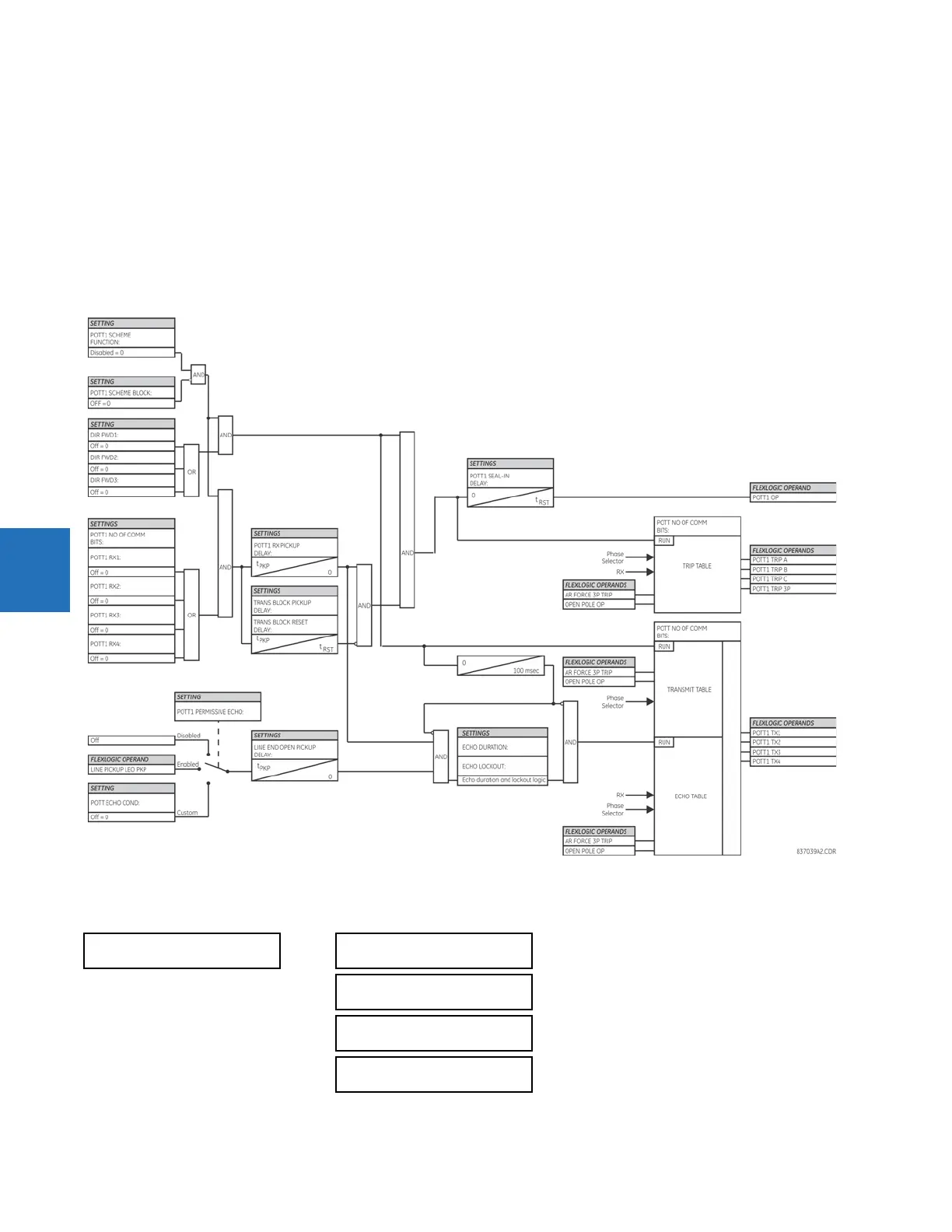
Figure 5-219: POTT1 (ground) scheme logic
5.8.12.6 Hybrid permissive over-reaching transfer trip
SETTINGS CONTROL ELEMENTS PILOT SCHEMES HYBRID POTT SCHEME
HYBRID POTT SCHEME
HYB POTT SCHEME
FUNCTION: Disabled
Range: Disabled, Enabled
HYB POTT BLOCK:
Off
Range: FlexLogic operand
HYB POTT PERMISSIVE
ECHO: Disabled
Range: Disabled, Enabled, Custom
HYB POTT ECHO COND:
Off
Range: FlexLogic operand
 Loading...


