CHAPTER 5: SETTINGS CONTROL ELEMENTS
L90 LINE CURRENT DIFFERENTIAL SYSTEM – INSTRUCTION MANUAL 5-393
5
Even though any FlexLogic operand can be used as BLK1 SCHME DIR FWD enabling the user to combine responses of
various protection elements or to apply extra conditions through FlexLogic equations,
BLK1 SCHME DIR FWD entries are
primarily meant to be the output operand from the Negative-Sequence Directional FWD IOC, Neutral Directional FWD IOC,
and the forward-looking distance over-reaching elements.
BLK1 SCHME DIR REV1-3 — This setting defines the FlexLogic operand of a protection element that is used for identifying
reverse faults, and thus, for initiating the blocking signal. Reverse-looking directional overcurrent protection elements or
reverse-looking distance elements can be used as
BLK1 SCHME DIR REV.
Even though any FlexLogic operand can be used as
BLK1 SCHME DIR REV enabling the user to combine responses of various
protection elements or to apply extra conditions through FlexLogic equations,
BLK1 SCHME DIR REV entries are primarily
meant to be the output operand from the Negative-Sequence Directional REV IOC, Neutral Directional REV IOC, non-
directional IOC, or reverse-looking distance elements.
Coordinate the selected protection element (or elements in combination) with the selection of DIR FWD. For all the forward
external faults seen by an element used as
BLK1 SCHME DIR FWD at one end of the line, the reverse-looking element used as
BLK1 SCHME DIR REV at the other end picks up and provides a blocking signal.
BLK1 FORCE TX STOP1-2 — This setting defines the FlexLogic operand of a protection element that is used for identifying
internal faults on the protected line, and thus, for stopping the blocking signal. Typically forward-looking under-reach
distance elements are used as
BLK1 FORCE TX STOP.
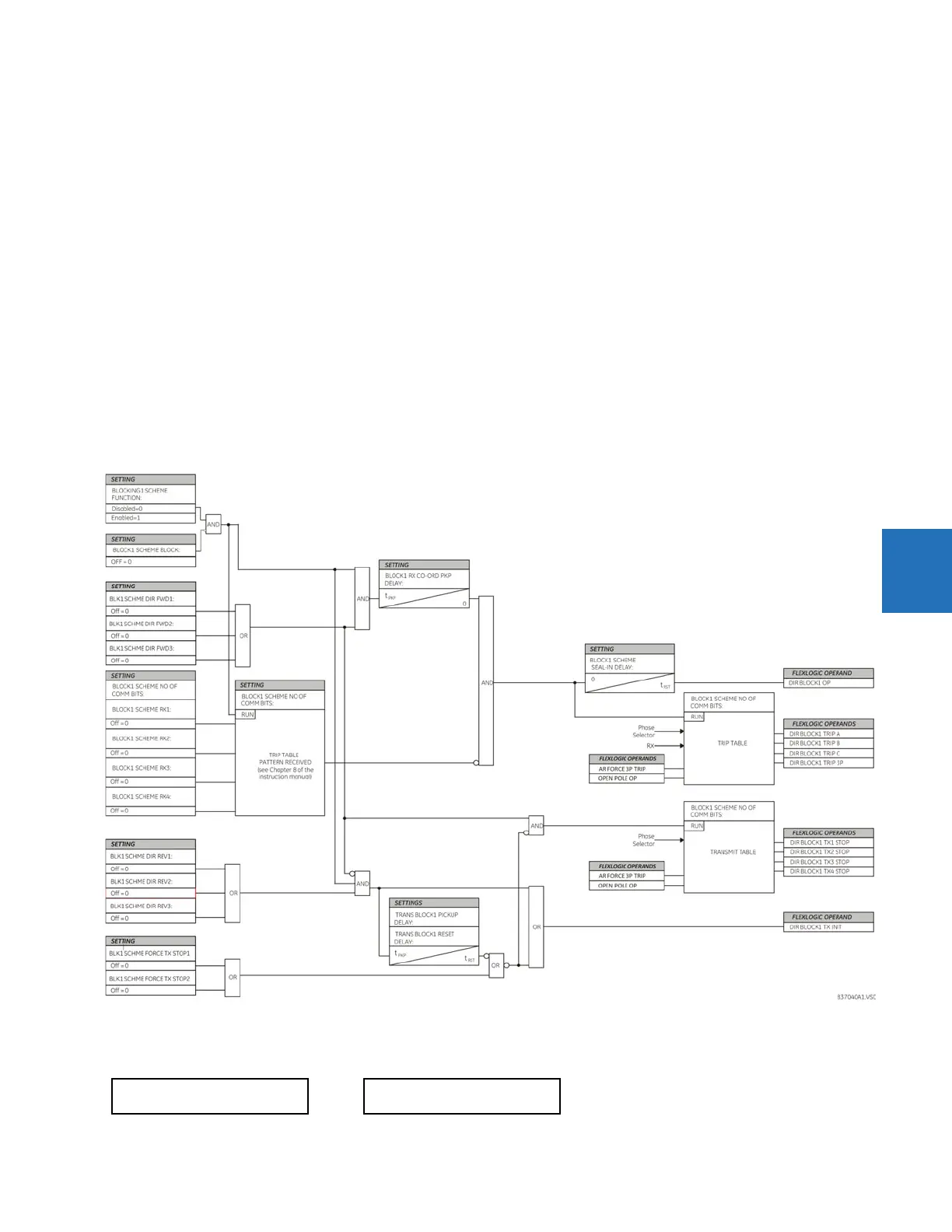
Figure 5-222: Directional comparison blocking1 scheme logic
5.8.12.9 Directional comparison unblocking
SETTINGS CONTROL ELEMENTS PILOT SCHEMES DCUB SCHEME
DCUB SCHEME
DCUB SCHEME
FUNCTION: Disabled
Range: Disabled, Enabled
 Loading...


