2. Setting Up for Phased Array Measurement
PHASOR XS Operating Manual Page 17
AMP COLOR PALET—Select the colors used to
represent ranges of amplitude values when sector
or linear scans are displayed.
VIDEO REVERSE—Reverse the orientation of Dis-
played Sector Scans (left to right) and Linear Scans.
Step 3: Press
under BACKGRND Submenu, then
press
next to one of the following functions:
COLOR—Select the display’s color scheme, which
is applied to the reading boxes.
COLOR LEG—Turn the displayed leg lines ON or
OFF
IMAGE BACKGRND—Sets the background color
displayed around the sector scan.
ASCAN COLOR—Select the A-Scan’s color
Step 4: To change the value of the select function,
continue pressing the corresponding
or turning the
function knob.
Step 5: Press
under STARTUP (located in the
CONFIG menu), then press
next to BRIGHTNESS.
Press
or turn the Function Knob to select settings
from 1 to 10.
Step 6: The selected function will remain at the
value last displayed.
2.3 Installing a Phased Array Probe
NOTE: Modifying certain settings related to probe or
scan configuration will require a recalculation of the
delay laws. When such a change is made, the modi-
fied function will turn red, indicating that the effect of
this change will not take affect until the new delay-law
calculation is carried out. To command a calculation,
press and hold
for three seconds or access the
SCAN PATT Submenu and press
next to the CALC
Function.
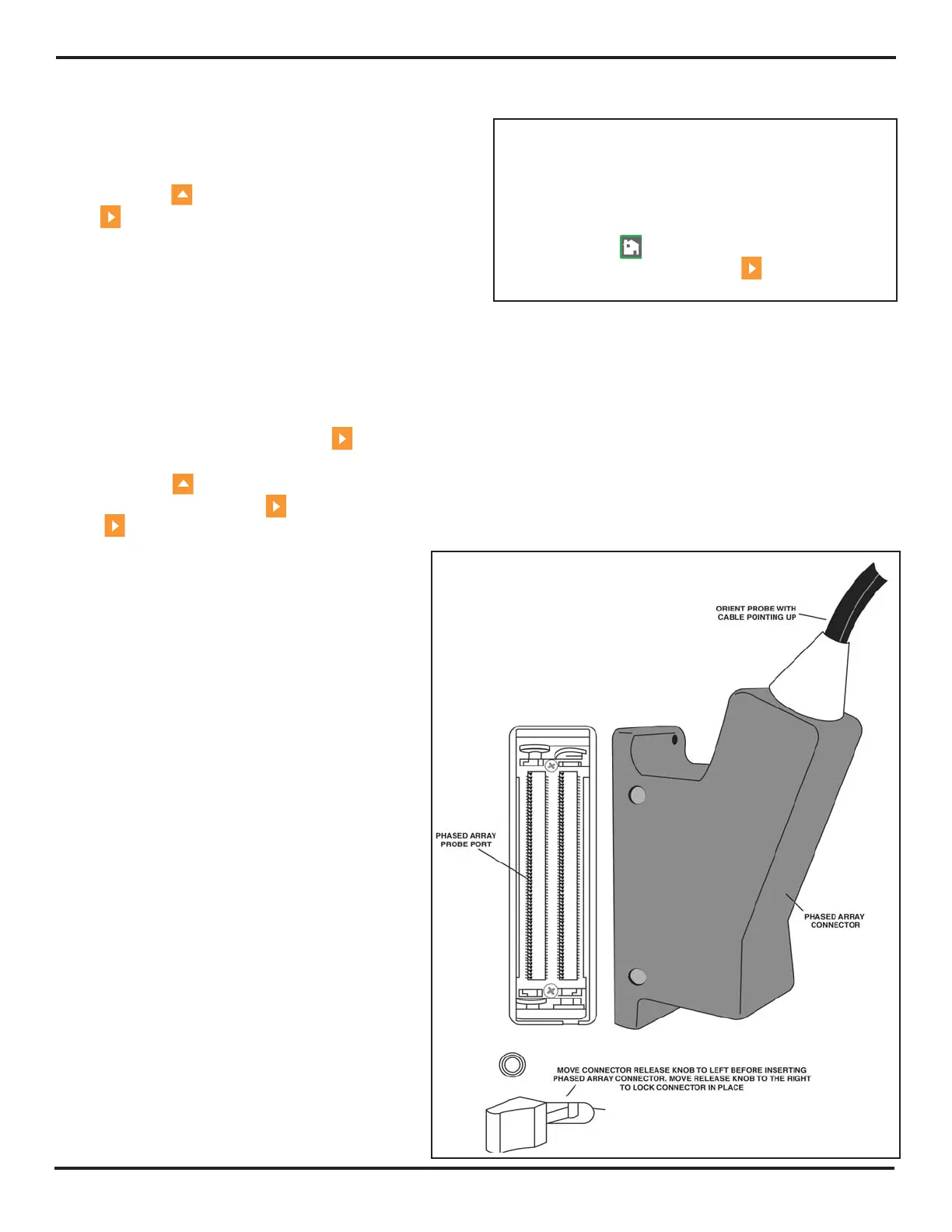
2.3.1 Connecting a Probe
When connecting a probe to the instrument, it’s not only
important that the probe’s physical connection be properly
made, but that the instrument is properly configured to
work with the installed probe. To install a phased array
probe, connect it to the front of the instrument. Be sure
to install it with the probe cable facing up and to operate
the probe-release lever as shown in
Figure 2-2.
FIGURE 2-2—Phased Array Probe Attachment

 Loading...


