2. Setting Up for Phased Array Measurement
PHASOR XS Operating Manual Page 27
2.7.2 Selecting the Pulser Width
(UT-PULSER-WIDTH)
The pulser width generally varies from 40 to 1000 nano-
seconds. A recommended starting point from which the
width setting can be adjusted is found by the following
equation:
PULSE WIDTH = 1000 ns with f in MHz
2f
For example, if a 2 MHz probe is used, the equation
becomes:
PULSE WIDTH = 1000 ns = 250 nanoseconds
2
.
2
for f = 2 MHz
To set a pulser width:
Step 1: Activate the PULSER Submenu (located in the
UT Menu) by pressing
below it. Functions will appear
down the left side of the display screen.
Step 2: Press
next to he function titled WIDTH.
Change the value by turning the Function Knob.
Step 3: The pulser WIDTH will be set to the value last
displayed.
2.7.3 Specifying the Receiver Frequency
(UT-RECEIVER-FREQUENCY)
Step 1: Activate the RECEIVER Submenu (located in the
UT Menu) by pressing
below it. Functions will appear
down the left side of the display screen.
Step 2: Press
next to he function titled FREQUENCY.
Change the value of the receiver frequency by continuing
to press
or by turning the Function Knob. You’ll note
that the following frequency settings are available:
• 2, 3, 4, 5 MHz—Select as required
• LOW PASS 4 MHz—Select to utilize a built-in low-
pass (LP) filter
• HIGH PASS 5 MHz—Select to utilize a built-in high-
pass (HP) filter
• BB 0.6–6.5 MHz—Select to utilize a built-in broad-
band (BB) filter
Step 3: The receiver frequency level will be set to the last
selection displayed.
2.7.4 Selecting a Rectification Mode
(UT-RECEIVER-ASCAN RECTIFY)
Rectification affects the orientation of the A-scan on the
display screen. The A-scan represents the sound pulse
(echo) that’s returned from the material being tested to
the instrument. The series of echoes looks like the
Radio Frequency (RF) signal that’s shown in
Figure 4-9.
Note that the RF signal has a negative component below
the axis, and a positive component above the axis. In RF
mode, the A-gate and B-gate can be positioned either
above or below the axis, to be triggered by a positive-
heading echo or a negative-heading echo.
Positive Half Rectification means that only the upper
(positive) half of the RF signal is displayed.
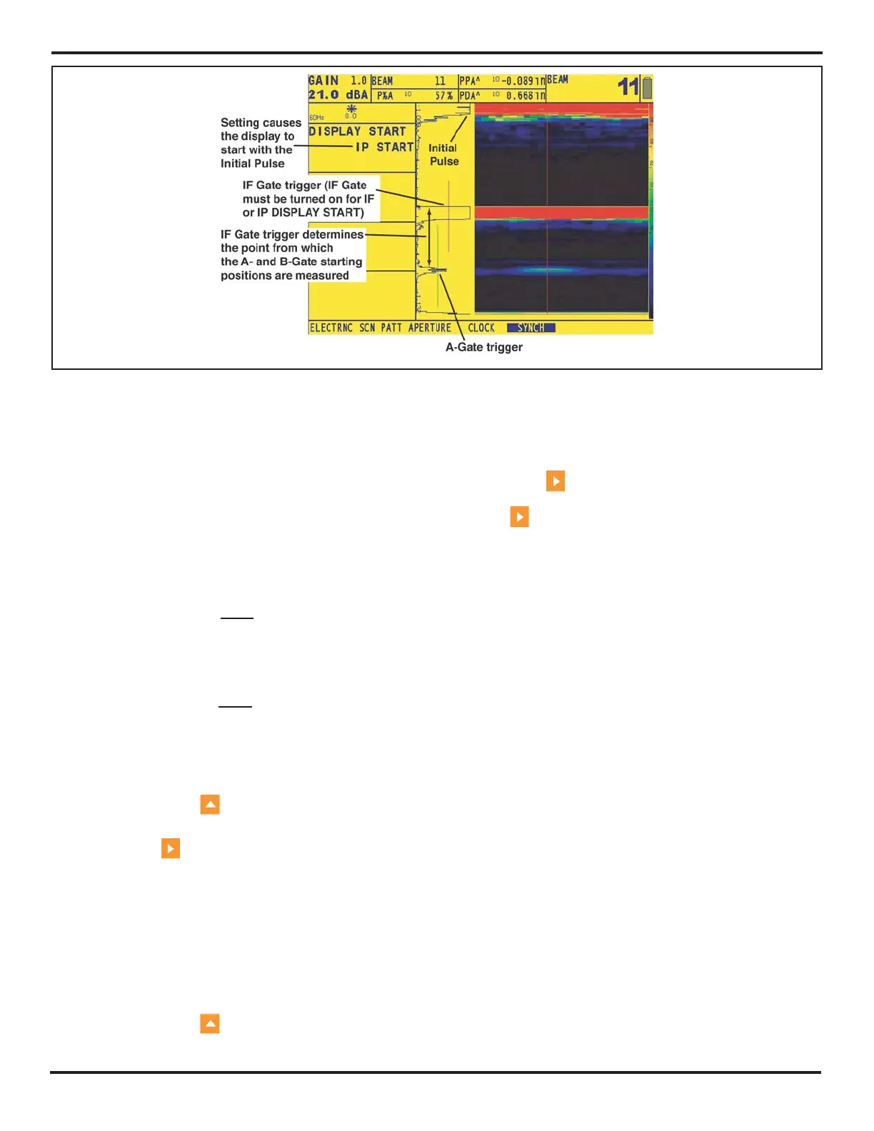
FIGURE 2-11—The DISPLAY START value can be set to IP, IF, or MATERIAL. When the IF Gate is turned on, the A-
and B-Gate starting points are based on the IF-Gate triggering echo. Note that both IF and IP DISPLAY START modes
accommodate variations in the initial-pulse-to-interface distance while the MATERIAL setting assumes a fixed distance
from the initial pulse to the test-piece interface.

 Loading...


