4. Conventional Operation: Menu System, Keypad, and Displays
Page 58 PHASOR XS Operating Manual
below it. Two functions will appear down the left side of
the display screen.
Step 3: Press
next to the function titled PRF MODE.
You’ll note that there are two options:
• AUTO—The instrument calculates and sets a pulser
firing rate at 75% of the maximum frequency pos-
sible based on range and material velocity.
• MANUAL—Allows the user to set the pulser fre-
quency. Unacceptable PRF settings will cause a
display prompt to appear.
Step 4: To manually set the Pulser Repetition Frequency,
press
next to the function titled PRF MODE and set it
to MANUAL. You may now adjust the PRF value by turn-
ing the function knob.
Step 5: The automatically calculated value (if PRF MODE
is set to AUTO) will be displayed in the function box.
NOTE: The PRF VALUE setting may be auto-
matically limited based on the user-selected pulser
voltage setting. This feature acts to limit signal
dissipation.
4.7.4 Selecting a Rectification Mode
Rectification effects the orientation of the A-scan on the
display screen. The A-scan represents the sound pulse
(echo) that’s returned from the material being tested to
the instrument. The series of echoes looks like the Radio
Frequency (RF) signal that’s shown in
Figure 4-9. Note
that the RF signal has a negative component below the
axis, and a positive component above the axis. In RF
mode, the A-gate and B-gate can be positioned either
above or below the axis, to be triggered by a positive-
heading echo or a negative-heading echo.
Positive Half Rectification means that only the upper
(positive) half of the RF signal is displayed.
Negative Half Rectification means that only the
bottom (negative) half of the RF signal is displayed. In
Figure 4-10, note that even though it’s the negative half
of the RF signal, it’s displayed in the same orientation as
a positive component. This is only to simplify viewing.
The signal displayed in the view identified as Negative
Reactance is the negative component of the RF signal.
Full-Wave Rectification combines the positive and nega-
tive rectified signals together, and displays both of them
in a positive orientation (
Figure 4-10).
Use the following procedure to select a rectification
mode
Step 1: Activate the SETUP Menu (located in the HOME
Menu) by pressing
below it.
Step 2: Select the RECEIVER submenu by pressing
below it. Four functions will appear down the left side of
the diplay screen.
Step 3: Press
next to the function titled RECTIFY
(
Figure 4-9). You’ll note that there are four options:
• NEG HALFWAVE—Shows the negative component
of the RF signal but displays it in a positive orienta-
tion
• POS HALFWAVE—Shows the positive component
of the RF signal
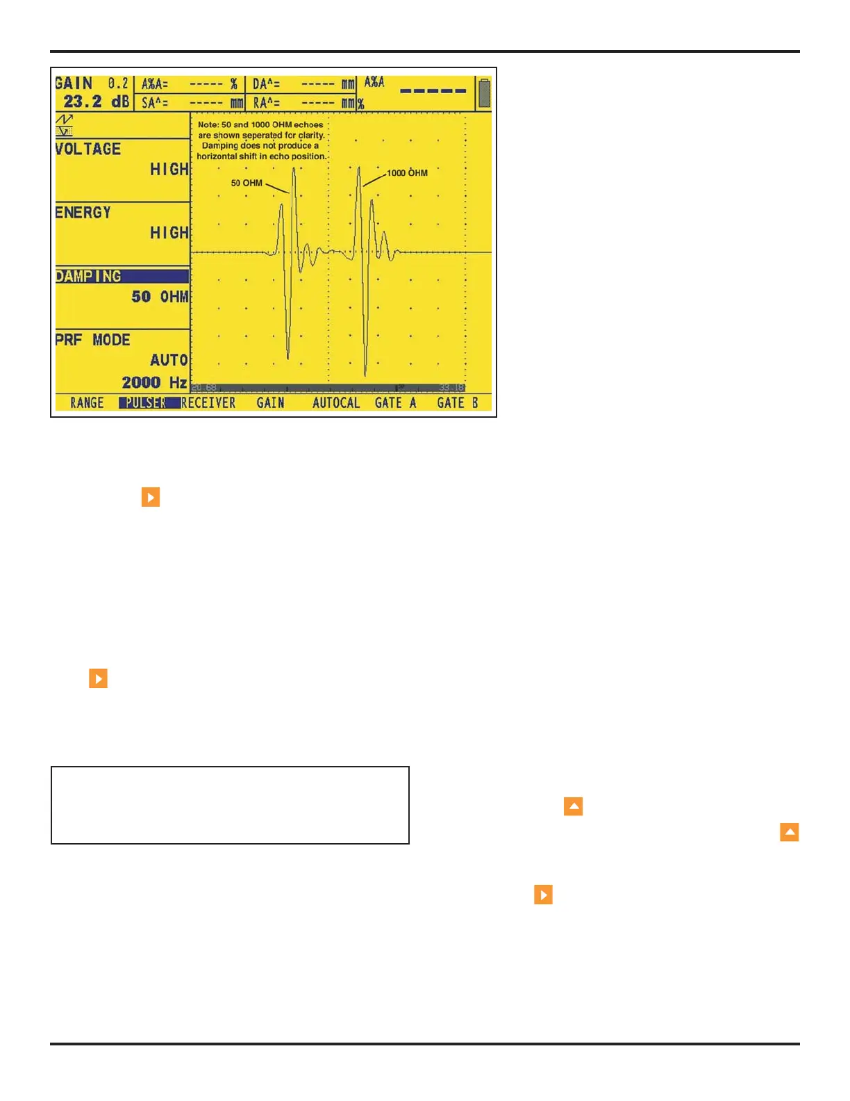
FIGURE 4-9—Typical
Effects of Damping
Changes

 Loading...


