6. Storing Data Sets and Generating Reports
PHASOR XS Operating Manual Page 89
6.7 Outputting via the RS-232 Serial
Port or Seven-Pin LEMO Connector
The serial port of a PC can connect with the instrument
via the RS-232 serial port located at the upper-rear corner
of the instrument. To output the 5-volt TTL #1 signal to
a connected PC you must connect the instrument to the
PC using the correct cable (RS-232-to-9 Pin Serial Printer
Cable). Note that the 5-volt output signal occurs on pin
#7 of the RS-232 port.
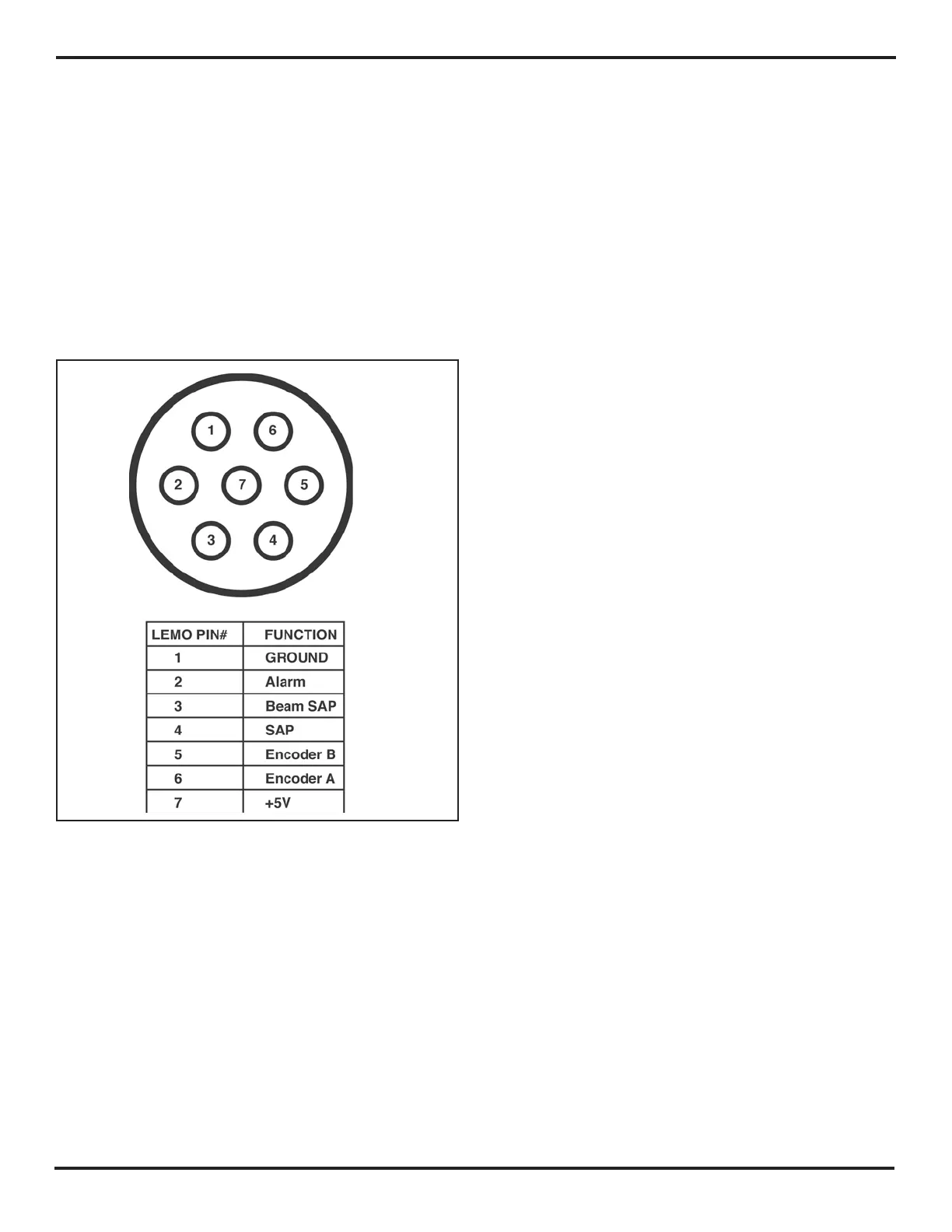
The seven-pin LEMO connector is located on the right
side of the instrument (above the Function Knob). This
connector’s pin assignments are shown in
Figure 6-4.
FIGURE 6-4—LEMO Connector Pin Assignments

 Loading...


