2. Setting Up for Phased Array Measurement
PHASOR XS Operating Manual Page 25
APERTURE – During a sector scan, these parame-
ters define the first element to be fired and the num-
ber of additional elements to fire at each angular
setting (or STEP). When performing a linear scan,
the first element to be fired and number of additional
elements in that STEP are defined, as well as the
total number of steps.
ANGULAR CORRECTED VIEW – Adjusts the
display to match the actual shape of the material
inspected during the sector scan.
2.6 Defining the Ultrasonic
Characteristics of the Displayed Scan
2.6.1 LEG Setting to Control the Scan
Range
The displayed sector or linear scan represents the reflec-
tion of sound off various features in the test piece. The
display range (distance traveled by the sound beam in the
test piece) is altered by adjusting the LEG setting. The ef-
fect of this adjustment is to show fewer (or additional) legs
as shown in
Figure 2-10. To modify the LEG setting,
Step 1: Make sure the COLOR LEG function (DISPLAY
Menu, BACKGRND Submenu) is set to ON. This causes
the leg lines shown in
Figure 2-10 to be displayed but is
not otherwise required to use the LEG feature.
Step 2: Press
to activate the HOME Menu. Then
press
next to the selection titled LEG.
Step 3: Turning the function knob will change the value
of LEG and reduce or expand the sound-path length dis-
played on the screen. If COLOR LEG is set to ON, you’ll
also notice the addition or removal of leg lines as the LEG
setting changes.
2.6.2 Setting the Display Delay
The DISPLAY DELAY function shifts the displayed scan
to ignore (or show) a portion of the scan. This function is
used to set the Instrument’s viewing window. To set the
display delay
Step 1: Activate the BASE Submenu (located in the UT
Menu) by pressing
below it.
Step 2: Press
next to the function titled DISPLAY
DELAY. Change the value of the delay by
turning the Function Knob, then press and hold
for three seconds to recalculate the delay laws.
You’ll note that the displayed Sector, Linear, or A-Scan
shifts in response to the setting change.
2.6.3 Defining the Display’s Starting
Point
The DISPLAY START Function sets the display’s start-
ing point to match the initial pulse or IF-Gate trigger (for
linear scans) or the position at which sound enters the
test material (in all scans). To select a display starting
position (
Figure 2-11):
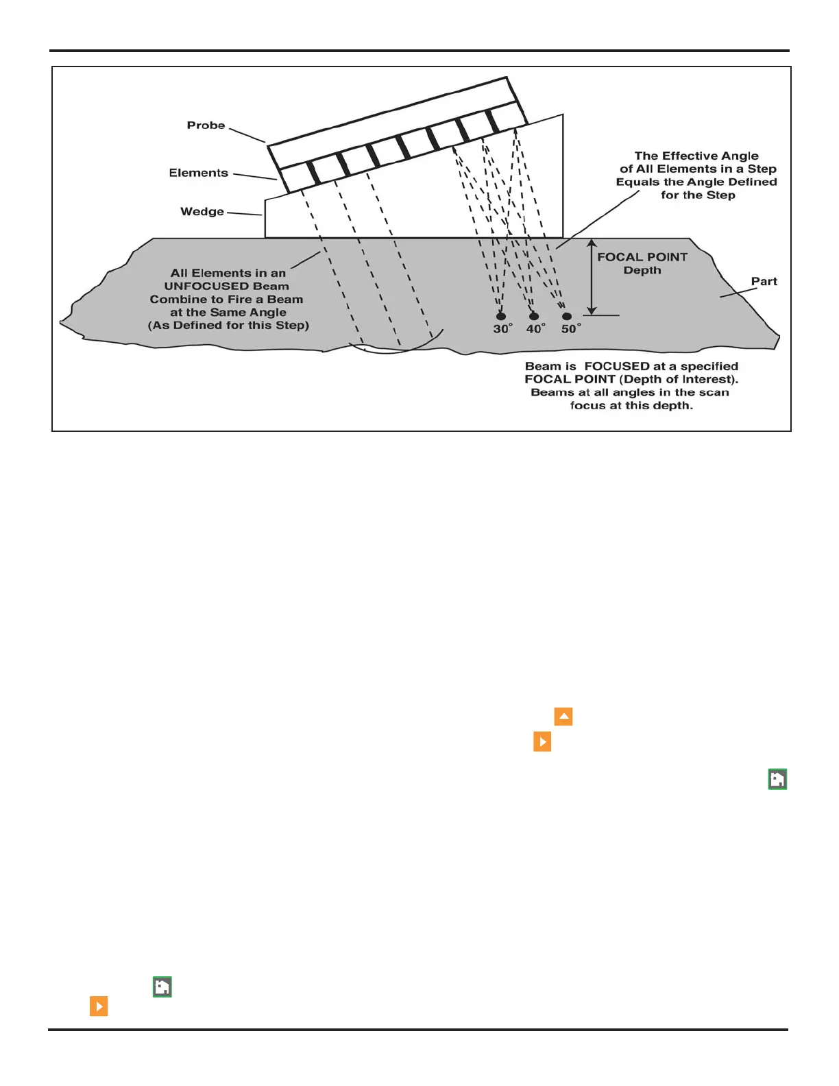
FIGURE 2-9—Sector Focal Point

 Loading...


