5. Making Conventional Measurements
Page 66 PHASOR XS Operating Manual
Defining Gate-Alarm Logic
(GATES-GATE MODE-GATE A or B LOGIC)
Each gate’s alarm can be triggered under one of two cir-
cumstances. Gate alarms can be set to trigger when an
A-Scan echo crosses the gate or when no echo crosses
the gate. Use the following procedure to specify gate
LOGIC settings:
Step 1: Activate the GATE MODE Submenu (in the
GATES Menu).
Step 2: Select the GATE LOGIC function you wish to
specify.
Step 3: Choose the gate-alarm triggering logic:
• POSITIVE—An A-Scan signal crosses the gate
• NEGATIVE—No A-Scan signal crosses the gate
• OFF—No alarm will be connected to the selected
gate
Step 4: Note that A- and B-Gates can be configured so
that either triggers the alarm.
Assigning Outputs / Alarm Indication Lights to
Gates (GATES-GATE MODE-OUTPUT SELECT)
A warning light appears on the front of the instrument (see
Figure 4-2 for light location). This light corresponds to an
OUTPUT, which is in-turn assigned to a gate alarm. When
an alarm is triggered, a warning light illuminates (except
when the GATE LOGIC is set to OFF). Use the following
procedure to indicate which gate activates the light:
Step 1: Activate the GATE MODE Submenu (in the
GATES Menu).
Step 2: Select the OUTPUT SELECT Function.
Step 3: Choose one of the following selections:
• A-GATE—Alarm light indicates when A-Gate’s
alarm triggers
• B-GATE—Alarm light indicates when B-Gate’s
alarm triggers
• A or B—Alarm light indicates when either A or B
Gate’s alarm triggers
Select Gate to Be Magnified when BVIEW Is
Pressed (EVAL-EVAL MODE-MAGNIFY GATE)
Pressing magnifies the A-Scan display so the assigned
gate spans the entire displayed range. To specify the gate
that should be magnified on demand:
Step 1: Activate the EVAL MODE Submenu (in the EVAL
Menu).
Step 2: Choose the MAGNIFY GATE function.
Step 3: Select GATE A or GATE B.
Step 4: Note that pressing BVIEW magnifies the display
so the selected gate spans the entire displayed range.
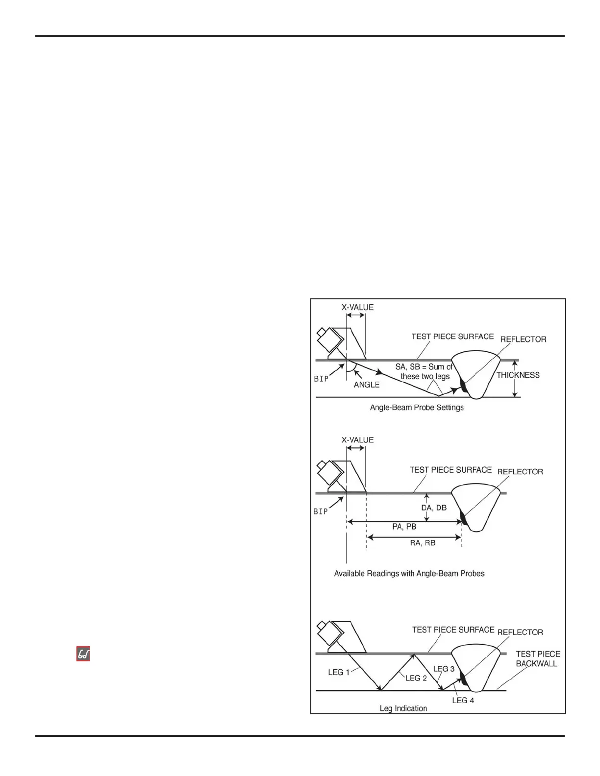
5.2 Using Angle Beam Probes and
the TRIG Menu
When connecting an angle beam probe to the instrument,
adjustments must be made for probe characteristics as
well as test-piece geometry. These features are shown
in
Figure 5-4 and include
• Probe Angle
• Probe’s X value (distance from the probe’s Beam
Index Point (BIP) to the front edge of its wedge.)
• Test-piece thickness
FIGURE 5-4—Angle Beam Flaw Detection

 Loading...


