2. Setting Up for Phased Array Measurement
Page 28 PHASOR XS Operating Manual
Negative Half Rectification means that only the
bottom (negative) half of the RF signal is displayed. In
Figure 4-9, note that even though it’s the negative half of
the RF signal, it’s displayed in the same orientation as a
positive component. This is only to simplify viewing.
Full-Wave Rectification combines the positive and nega-
tive rectified signals together, and displays both of them
in a positive orientation.
Use the following procedure to select a rectification
mode:
Step 1: Activate the RECEIVER Submenu (located in the
UT Menu) by pressing
below it. Functions will appear
down the left side of the display screen.
Step 2: Press
next to the function titled ASCAN REC-
TIFY. You’ll note that there are four options:
• NEG HALFWAVE—Shows the negative component
of the RF signal but displays it in a positive orienta-
tion
• POS HALFWAVE—Shows the positive component
of the RF signal
• FULLWAVE—Shows the positive and negative
halves of the RF wave, but both are oriented in the
positive direction
• RF—Shows the echo with no rectification
Step 3: Select the rectification method.
2.8 Managing Gates for Phased Array
Operation
Setting the position and characteristics of the IF, A, and
B-Gates for phased-array operation requires access to the
UT Menu. The GATEMODE and GATE POS menus control
not only the location of the gates but also the alarms and
other features activated when an A-Scan is triggered.
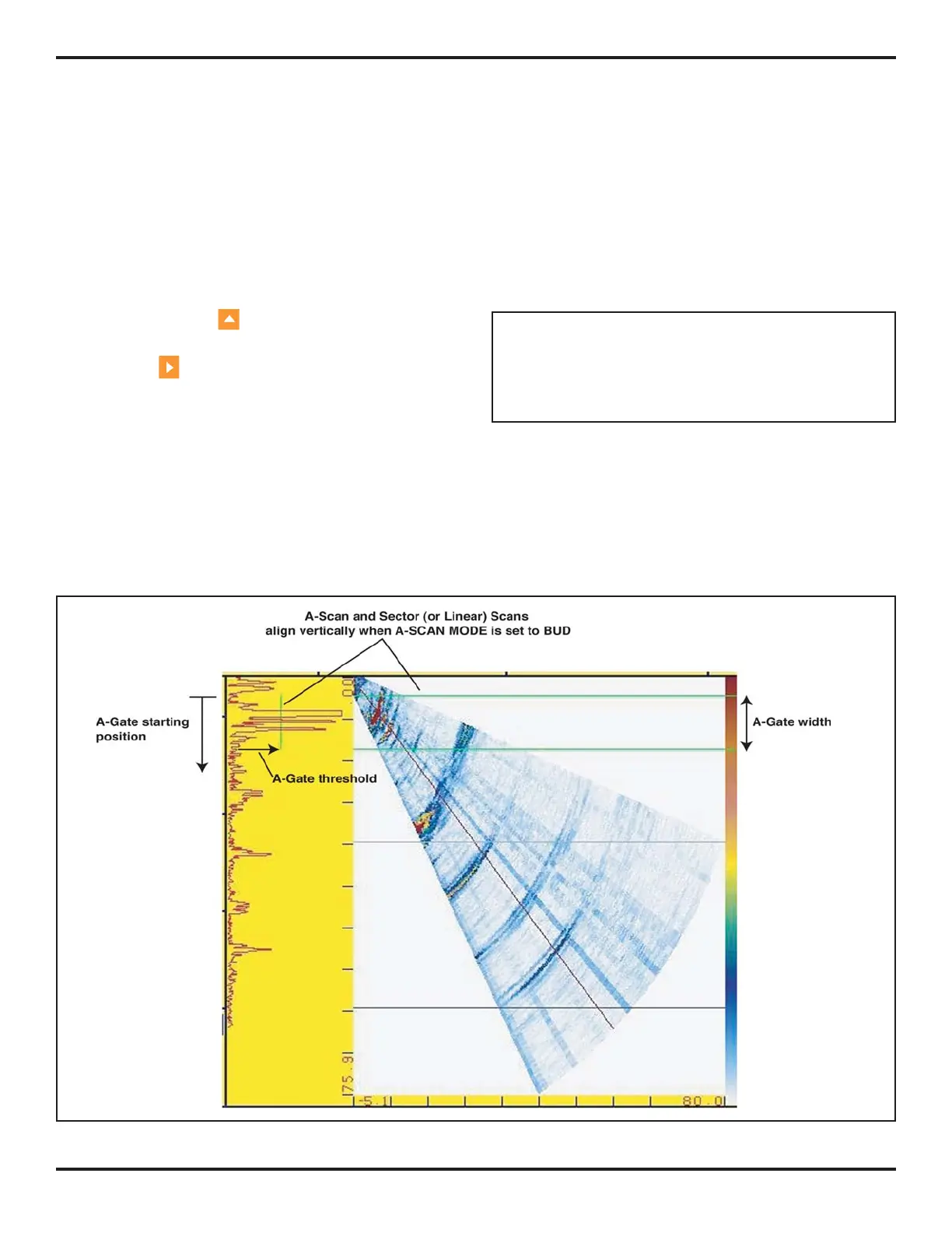
NOTE: With a sector scan displayed, gate width and
starting position are measured (and displayed) with
respect to material depth (not sound-path depth). Mate-
rial depth is measured perpendicular to the test piece’s
contact surface for all angles in the scan.
2.8.1 Positioning Gates
Use the following procedures to set the position of the IF,
A, and B-Gates. The effect of each gate-positioning func-
tion is shown in
Figure 2-12.
FIGURE 2-12—Gate position and width can be adjusted as shown here.

 Loading...


