5. Making Conventional Measurements
Page 72 PHASOR XS Operating Manual
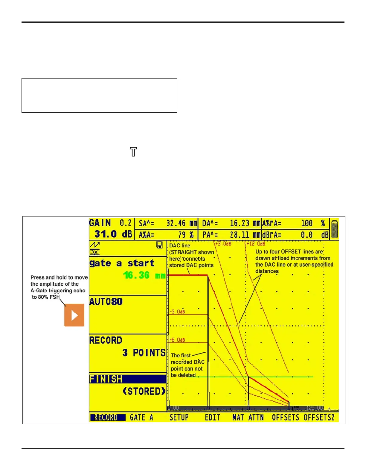
Step 3: The DAC curve can appear as a series of straight
line segments (
Figure 5-7) joining the stored DAC points
or as a curved (linear in gain – as shown in
Figure 5-6)
line that’s based on these points. Access the DAC TYPE
function, located in the SETUP Submenu, to display the
desired DAC curve type.
NOTE: To operate in TCG/DAC mode, a DAC curve
must first be generated. After the DAC curve is gener-
ated, the TCG feature can be accessed by setting the
TCG/DAC function’s value to TCG.
5.10 Using TCG
When the TCG function is in use, echoes from equally
sized reflectors appear as the same height on the A-Scan
display. When operating in TCG mode
will appear on
the display screen. Before using the TCG function do the
following:
Step 1: The instrument/probe combination has been cali-
brated and all instrument settings (PULSER, RECEIVER,
etc.) have been made. Changing these settings after the
TCG reference points are input will affect the accuracy
of measurement.
Step 2: TCG reference points (up to 15) must be recorded.
This process allows the instrument to calculate and com-
pensate for the effect on material depth on reflector-echo
height. The dynamic range of the TCG function is 60 dB.
Maximum curve slope is 12 dB per microsecond. Succes-
sive data points do not have to decrease in amplitude. That
is, the DAC/TCG curve does not have to have a constantly
descending slope.
5.10.1 Generating the TCG Reference
Curve
TCG reference points are derived from the points used
to create the DAC curve. Points are typically taken from
a standard with equally sized reflectors (holes) located at
various material depths. The primary echo from each of
these points (for up to a total of 15 echoes) are recorded.
When TCG is active, the instrument compensates for dif-
ferent material thickness by applying a varying gain level
to echoes at material depths other than the baseline depth.
Only one DAC curve can be stored at a time.
FIGURE 5-7—Storing at least two DAC points allows you to generate a curved or straight (shown here) DAC line and
corresponding offset lines.

 Loading...


