5. Making Conventional Measurements
PHASOR XS Operating Manual Page 79
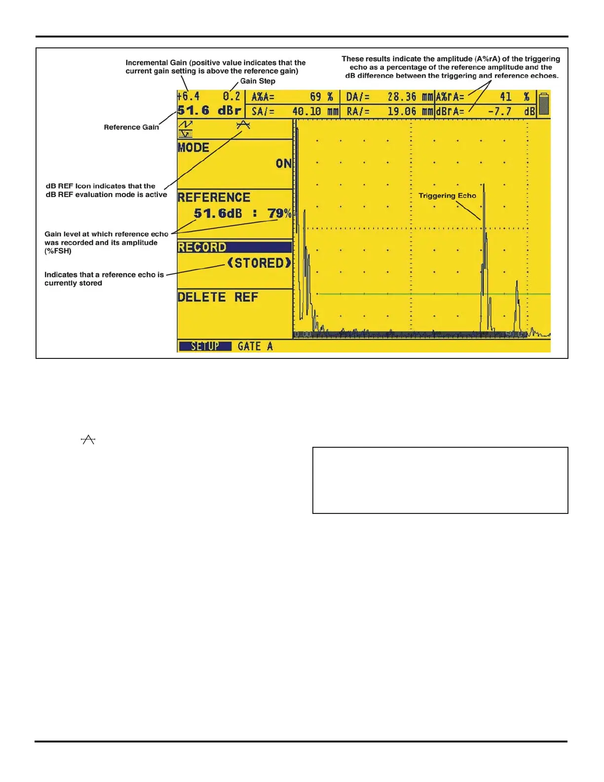
Once dB REF is activated, the Gain-Display Window lists
both the Reference Gain and Incremental Gain levels.
Also, the
icon will appear. The Reference Gain re-
mains constant throughout the dB REF session while
the Incremental Gain value changes as the Gain Knob is
rotated (
Figure 5-11).
After dB REF is activated, any amplitude measurements
are stated in relation to the reference echo amplitude.
Available amplitude readings (see
Section 5.3 to change
display-box reading values) when operating in dB REF
mode are
• dBrA—dB difference between the reference echo
and the highest echo to cross A-Gate.
• A%rA—Amplitude of the signal crossing the A-Gate
as a percentage of the reference amplitude.
• dBrB—dB difference between the reference echo
and the highest echo to cross B-Gate.
• A%rB—Amplitude of the signal crossing the B-Gate
as a percentage of the reference amplitude.
5.16 AWS D1.1 Weld Rating Evaluation
Mode
NOTE: Result-evaluating features, such as AWS
D1.1 / D1.5, are first selected by the user via the EVAL
MODE function (located in the EVAL Menu). The se-
lected evaluation feature’s menu then appears in the
HOME Menu.
This feature allows analysis of welds according to AWS
specifications D1.1 or D1.5 and provides a D1.1 or D1.5
rating. The AWS D1.1 feature is accessed via the HOME
Menu. The feature utilizes four AWS-specified variables
including:
A INDICATION—Gain (in dB) required to position an
A-Scan echo’s peak (from the measured reflector) at an
amplitude equal to the reference amplitude (between 10
and 90% of full screen height)
B REFERENCE—Gain (in dB) required to position an
AScan echo’s peak (from the reference reflector) at the
userselected amplitude (between 10 and 90% of FSH)
FIGURE 5-11—dB Ref capabilities

 Loading...


