GE RAFT VOLUSON™ P8/VOLUSON™P6
DIRECTION 5775469, R
EVISION 3 DRAFT (JULY 19, 2018) BASIC SERVICE MANUAL
5-34 Section 5-6 - OPIO (User Interface)
Section 5-6
OPIO (User Interface)
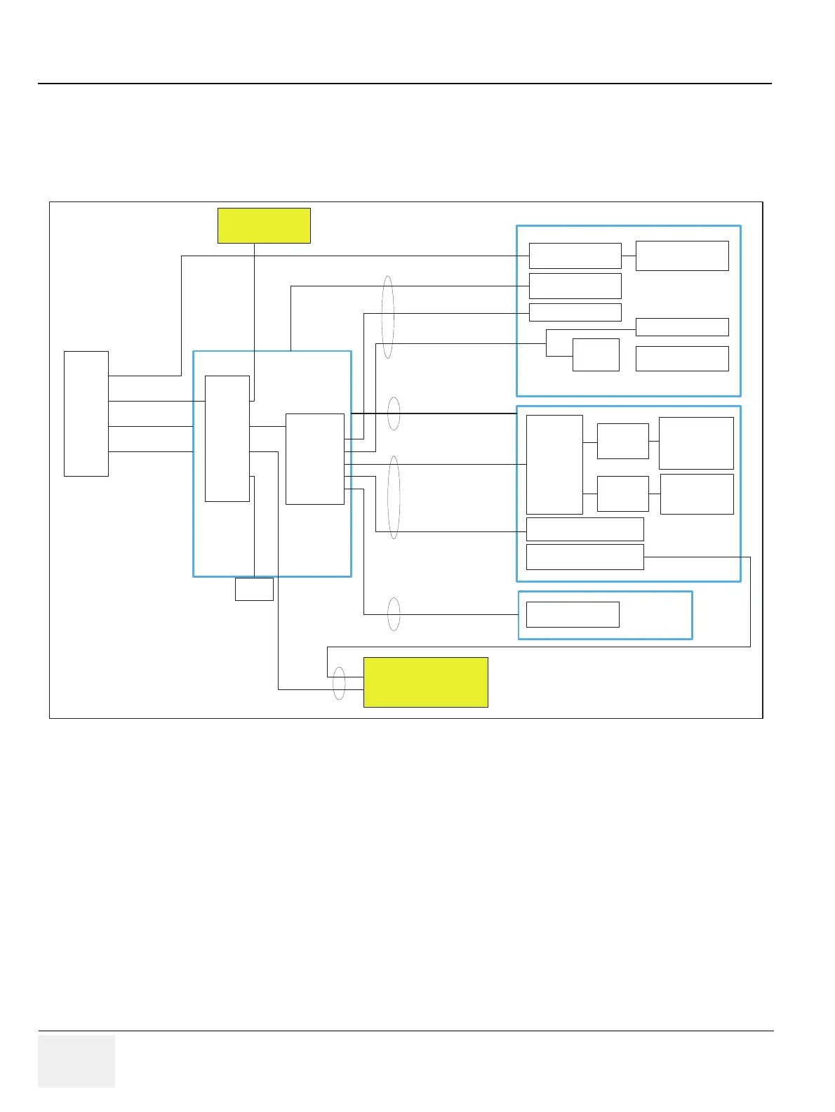
5-6-1 OPIO Block Diagram
The Voluson™ P8/Voluson™P6 OPIO (User Interface) consists of the following electronic
subassemblies and/or functional components:
• Upper Keyboard OPIO:
- Power ON/OFF control
- 2 USB 2.0 ports
- Configurable 9 buttons
• Lower Keyboard OPIO:
- 4 port USB 2.0 Hub controller
- Slide pots TGC with zero raster position
- Rotary Encoders with integrated push buttons
- USB Trackball (2”) with dedicated buttons to emulate standard three button mouse
- USB standard alphanumeric keyboard
- LED Indicators with wide range dimming
Figure 5-13 Main OPIO - Block Diagram
Micro
Controller
(USB)
USB HUB Down Stream(2)
Power LED(4)
Function S/W (9)
LED
Control
Backlight
&
Highlight LED
(174)
Encoder (10)
WHEEL(1)
LED
Control
Atmega
Function S/W (40)
Trackball S/W (3)
TGC (8)
USB
Trackball
USB
HUB
ECG
A/N Key
Stanby
Backlight LED
(36)
CPLD
HOST
HUB
SUB
MAIN
TGC
8 wire (USB (4) + LED backlight)
* USB-2
Communication
* USB-1
Communication
* +12V Power
* Stanby 3.3V
USB Cable
* Stanby 3.3V
26Pin Flat Cable
Power Cable
Assembly 6P Wire
Asynchrous Serial
8-Bit Serial
26Pin Flat Cable
10P Flat Cable
.

 Loading...


