GE DRAFT VOLUSON™ P8/VOLUSON™P6
DIRECTION 5775469, R
EVISION 3 DRAFT (JULY 19, 2018) BASIC SERVICE MANUAL
Chapter 8 - Replacement Procedures 8-55
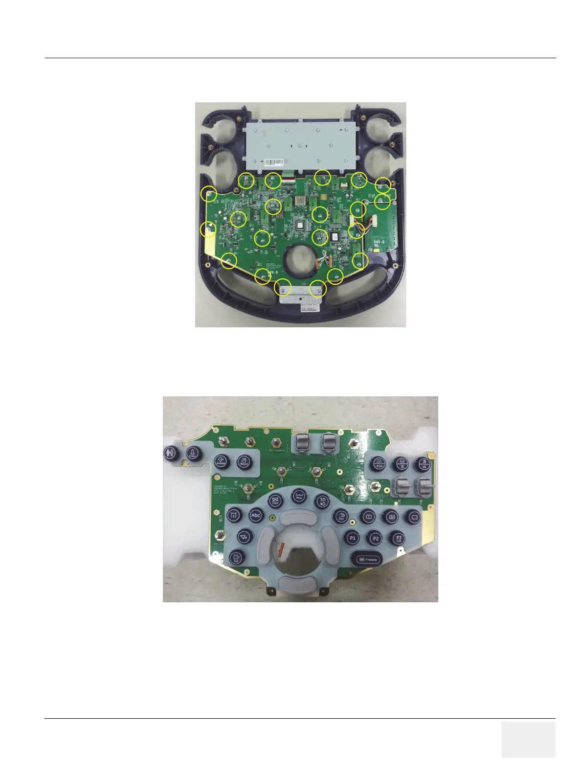
7.) After removing trackball, unscrew 21 screws and disconnect TGC calbe. And lift up the main
keyboard circuit board. Refer to the figure below.
8.) Remove the button to be replaced. Refer to the figure below.
8-18-4 Installation Procedure
Install a new part in the reverse order of removal procedure.
Figure 8-70 Lifting up the main keyboard circuit board after unscrewing 21 screws and
disconnecting TGC cable
Figure 8-71 Removing the button

 Loading...


