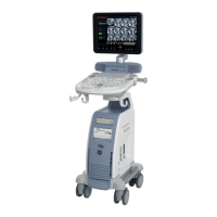
GE DRAFT VOLUSON™ P8/VOLUSON™P6
DIRECTION 5775469, R
EVISION 3 DRAFT (JULY 19, 2018) BASIC SERVICE MANUAL
Chapter 3 - Setup Instructions 3-31
Section 3-7
Printer Installation
NOTE: For Connection schemes refer to Section 3-5 "Connection of Auxiliary Devices" on page 3-11.
For further installation instructions see:
• Section 3-7-1 "Installing the Digital Black & White Printer" on page 3-31
• Section 3-7-2 "Installing the Digital Color Printer" on page 3-31
• Section 3-7-3 "Installing the Network Color laser Printer" on page 3-32
• Section 3-7-6 "Printer Installation manually" on page 3-48
• Section 3-7-7 "Adjustment of Printer Settings" on page 3-49
NOTE: The Bluetooth Printer Connection set MUST NOT be installed by the user! Bluetooth installation please
contact your local distributor or GE service representative.
If a a Desk Jet printer(e.g., HP Officejet 100) is connected directly via an USB-cable, use the AC mains
power outlet privided by the Voluson P-series system (auxiliary output). This ensures medical grade
separation from AC mains.
3-7-1 Installing the Digital Black & White Printer
1.) Power off/Shutdown the system as described in: Section 3-6-3 on page 3-28.
2.) Connect the printer as described on page 3-13.
3.) Verify correct printer settings; Section 3-7-7 "Adjustment of Printer Settings" on page 3-49
4.) Assign the printer to the remote keys P1, P2, P3; see Section 3-7-8 "Remote Control Selection" on
page 3-53
3-7-2 Installing the Digital Color Printer
1.) Power off/Shutdown the system as described in: Section 3-6-3 on page 3-28.
2.) Connect the printer as described on page 3-15
3.) Verify correct printer settings; Section 3-7-7 "Adjustment of Printer Settings" on page 3-49
4.) Assign the printer to the remote keys P1, P2, P3; see Section 3-7-8 "Remote Control Selection" on
page 3-53.
After each installation, the leakage currents have to be measured according to IEC
60601-1, UL 60601-1, IEC 62353, ANSI/AAMI ES60601-1 or other relevant standard.
 Loading...
