GE RAFT VOLUSON™ P8/VOLUSON™P6
DIRECTION 5775469, R
EVISION 3 DRAFT (JULY 19, 2018) BASIC SERVICE MANUAL
3-30 Section 3-6 - Completing the Set Up
3-6-4 Transducer Connection
NOTE: When the probe is connected, it is automatically activated.
Once connected, the probes can be selected for different applications.
Connect a transducer to one of the three rightmost transducer receptacle as follows:
1.) Inspect the probe and probe socket to verify that it is free of debris.
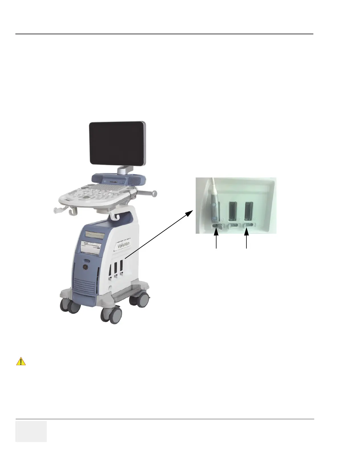
2.) Ensure that the probe locking lever is at left position, as shown Figure 3-19.
3.) Insert the connector on the receptacle, and move lever to the right position to lock probe.
4.) Carefully position the probe cord so that it is free to move and is not resting on the floor.
NOTE: Prior to connecting or disconnecting a probe, freeze the image.
It is not necessary to turn OFF power to connect or disconnect a transducer.
Figure 3-19 Transducer Connection
!! CAUTION:
Do not bend the probe cable acutely. Fault conditions can result in electric shock hazard.
Do not touch the surface of probe connectors which are exposed when the probe is removed.
Do not touch the patient when connecting or disconnecting a probe.
Tranducer locked
(locking lever in
right position)
Tranducer unlocked
(locking lever in
left position )

 Loading...


