January 2008
4-8 Setup and Calibration
Setting Up the System
Analog Output
The system analog output is not normally used for XDP applications.
However, if you do intend to use this output, it may be configured by
entering the User Program, as described on page 3-4, and proceeding
as follows:
Note: See Appendix B, Additional Wiring Connections, for
instructions on wiring the system analog output.
Note: “Lock All” and “Versions” menu options also appear on the
above list.
Note: The “Backlight” and “Comm” options are also available in
the above list box.
The following analog output features may be set in this menu:
• Analog Output Type: configure the system analog output for a
0-20 mA, 4-20 mA or 0-2 V output device
• Zero Setpoint: enter the live measurement value that corresponds
to the low end of the system analog output range.
• Span Setpoint: enter the live measurement value that corresponds
to the high end of the system analog output range minus the zero
setpoint.
• Test: manually generate a system analog output with a known value.
• Zero Trim: adjust the system analog output to equal the low end
of the recorder range.
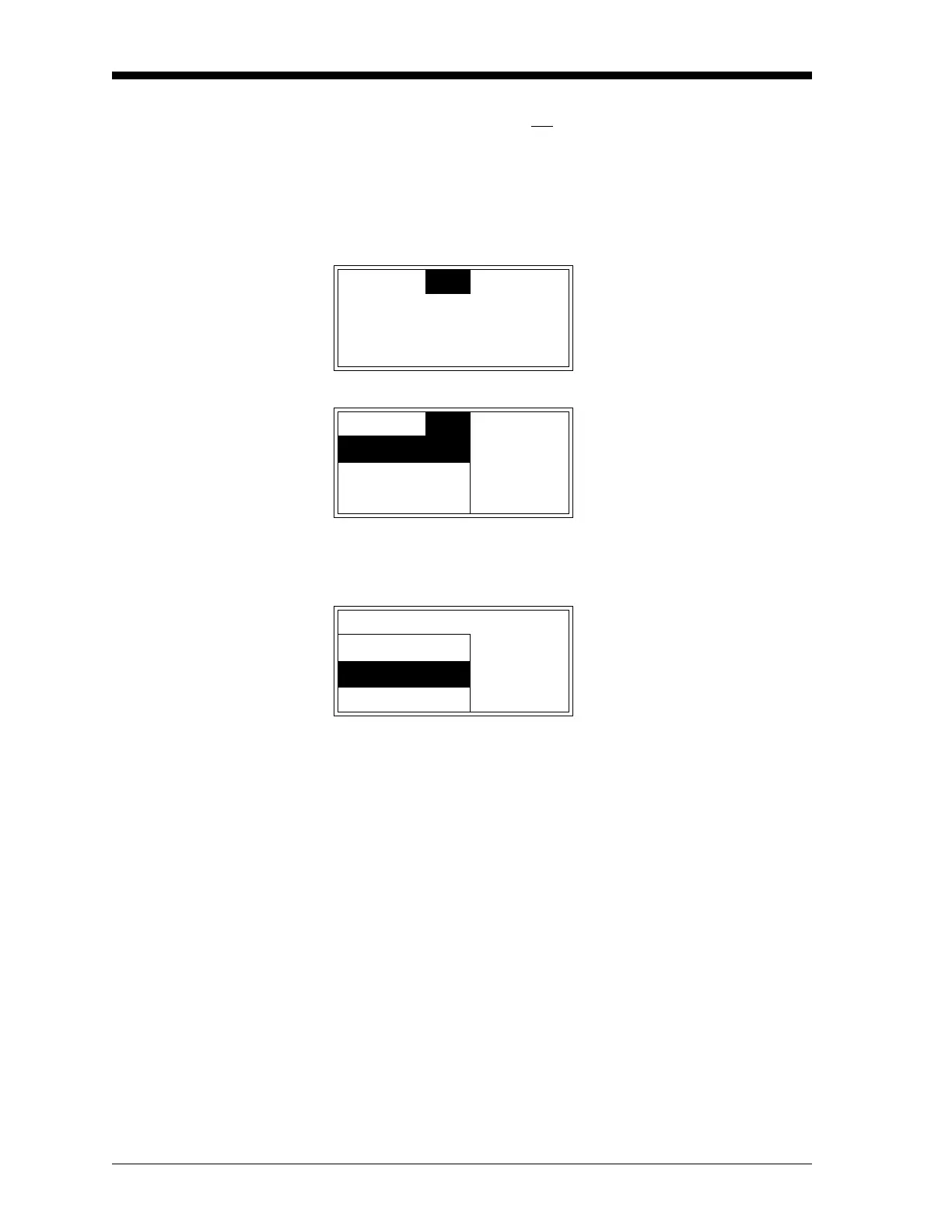
Cal
Opt
Disp Use the [W] and [X] keys to
select
[Opt] and press [ENTER].
Cal
Opt
Disp Use the [S] and [T] keys to
select
[User] and press [ENTER].
User
Lock Menus
User Use the [
S] and [T] keys to
select
[Analog Output] and
press
[ENTER].
Fault Alarm
Analog Output
Contrast

 Loading...


