Page 34
CDi DriveCore Series Operation Manual
Using HiQnet Audio Architect
Main CDi DriveCore Control Panel
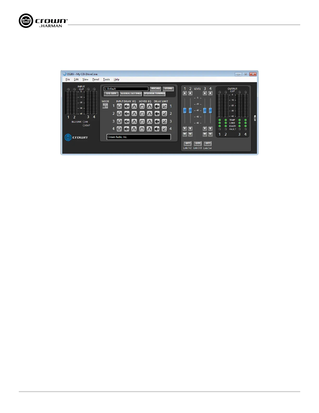
Double-clicking the CDi DriveCore image from the Room window (see Figure 31) will open the Main CDi DriveCore Control panel. Figure 34 shows the
4-channel version of the Main CDi DriveCore Control panel. The CDi DriveCore amplifiers include Digital Signal Processing (DSP), multiple input/output
routing options, and a comprehensive diagnostics feature set. All of these features can be accessed from the Main CDi DriveCore Control panel.
Figure 34: Main CDi DriveCore Control panel (4-channel amp model shown)
1� Level Faders
These faders set the output signal level of each channel and
correspond with the levels set using the front panel ENCODER.
2� Link Buttons
Links the Level faders and Mute buttons for ganged operation.
3� Mute Buttons
Mutes the corresponding output channel.
4� Input Meters
These meters display input signal level, and range from -40dBFS to
0dBFS. Each input channel has the following monitors:
• Peak and RMS Meters: The wider left meter shows RMS level
and the right meter shows peak level.
• Clip Indicator: Lights to indicate input clipping.
5� Output Meters
These meters display output signal level, and range from -40dBFS
to 0dBFS. The meters are scaled so that 0dBFS is referenced to the
full rated output voltage of the amplifier. Each output channel has the
following monitors:
• Peak and RMS Meters: The wider left meter shows RMS level
and the right meter shows peak level.
• Clip Indicator: Lights to indicate output clipping.
6� Indicators
a� BLU Link (In/Out): Available only on BLU link CDi DriveCore
models, these indicators light when the BLU link input and
output ports have established a link with the BLU link bus.
b� Temp: Indicates the temperature of an amplifier channel and
provides warning when an amplifier channel is too high and
near shutdown. These indicators may light one of the following
colors:
• Green: Thermal temperature is less than 80º C.
• Yellow: Thermal temperature is between 80-100º C.
• Red: Thermal temperature is greater than 100º C.
c� Limit: Lights when the amplifier's output signal is being
limited by the clip limiter, LevelMAX peak/rms/thermal speaker
limiters, or the amp thermal protection limiter.
d� Ready: Lights when the amplifier is on and ready to supply
power.
e� Fault: Lights when the amplifier detects a fault and enters a
fault state. See
"System Protection" on page 72 for
more information on the various types of possible faults.
7� DSP Buttons
Double-clicking any of these buttons will open the corresponding
DSP control panel, where DSP settings can be edited.
8� Other Buttons
a� Basic/Normal View (Arrow Button): Collapses or expands
the window.
b� Mode: Opens the Amplifier Mode Settings panel, where input
wiring and output operation can be configured.
c� Signal Generator: Opens the Signal Generator panel.
d� Global Settings: Opens the Global Settings panel (see
"Amplier Information" on page 35).
e� Speaker Tunings: Allows a speaker tuning to be selected
for each output to optimize DSP settings for particular speaker
models.
f� Recall: Loads a device preset.
g� Store: Stores a device preset.
Many of these functions will be further explained on the following pages.
 Loading...