Page 69
CDi DriveCore Series Operation Manual
Using the GPIO Control Port
Using the GPIO Control Port
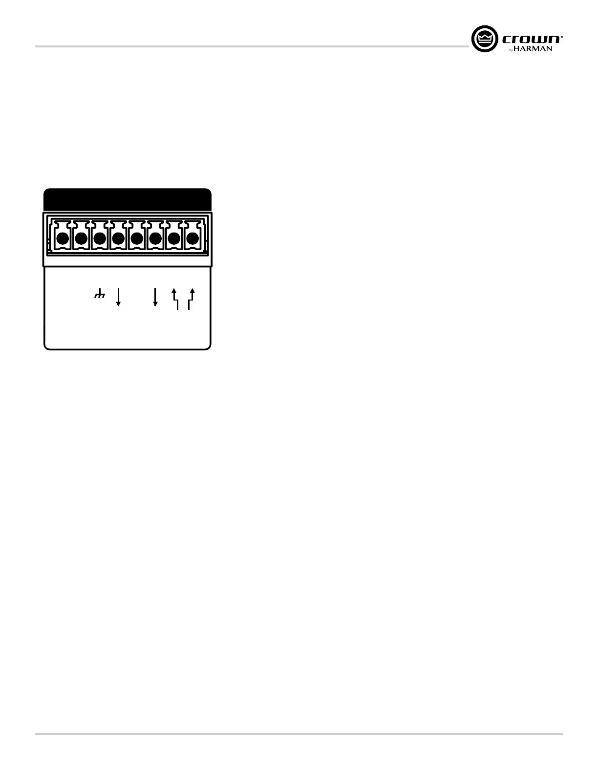
CDi DriveCore amplifiers come with a 2-in, 2-out General Purpose In/Out (GPIO) control port in the form of a block connector. The Control port has
multiple uses which include fault status reporting, device preset selection, output muting, and more. Control ports are configured using the Audio Architect
software.
GPIO Pinout, Specification, Use, & Configuration
SERIAL NUMBERSERIAL NUMBER
BAR CODE
100-240V
~ 50/60Hz 350W
1718 W. MISHAWAKA RD.
ELKHART IN 46517 USA
CAUTION - TO REDUCE THE RISK OF ELECTRIC
SHOCK, GROUNDING OF THE CENTER PIN
OF THIS PLUG MUST BE MAINTAINED
ATTENTION - POUR RÉDUIRE LE RISQUE DE CHOC
ÉLECTRIQUE LA FICHE CENTRALE LA PRISE DOIT ÊTRE
BRANCHÉE POUR MAINTENIR LA MISE À LA TERRE
WARNING
-
TO REDUCE THE RISK
OF FIRE OF ELECTRICAL SHOCK, DO
NOT EXPOSE THIS EQUIPMENT TO
RAIN OR MOISTURE.
AVERTISSEMENT
- ENERGIE
ELECTRIQUE DANGEREUSE` VOIR LE
CAHIER D’INSTRUCTIONS.
APPARATET MA TILKOPLES JORDET
STIKKONTAKT.
APPARATEN SKALL ANSLUTAS TILL
JORDAT UTTAG.
LAITE ON LIITETTÄVÄ
SUOJAKOSKETTIMILLA
VARUSTETTUUN PISTORASIAAN.
RISK OF ELECTRIC SHOCK
DO NOT OPEN
AVERTISSEMENT: RISQUE DE CHOC
ELECTRIQUE - NE PAS OUVRIR
CLASS 2 OUTPUT WIRING PERMITTED.
THIS DEVICE COMPLIES WITH PART 15 OF THE FCC RULES.
OPERATION IS SUBJECT TO THE FOLLOWING CONDITIONS.
1) THIS DEVICE MAY NOT CAUSE HARMFUL
INTERFERENCE.
2) THIS DEVICE MUST ACCEPT ANY INTERFERENCE
WARNING
OUTPUTOUTPUT INPUT
2 14 3
2 1
DUALDUAL
BRIDGE
OUTPUT
WIRING
ETHERNET
100Mb
ACT
GPIO/AUX
OUT
12
IN
3
AMP STATUS
7
+3.3V
45
IN
6
SLEEP
8
PIN 1 (Output 1): 0VDC to +3.3VDC output. Output impedance = 1KΩ pullup to +3.3V. This pin is used for fault reporting. If a fault occurs in the
amplifier, this pin will change from a low/false state to a high/true state. Polarity can be inverted when reversed functionality is required. See "Amplier
Information" on page 35
for information on inverting this output.
PIN 2 (Output 2): 0VDC to +3.3VDC output. Output impedance = 1KΩ pullup to +3.3V. This pin is used by Audio Architect and compatible HiQnet wall
controllers for generic output control functions. The functionality of this output is tied to the Manual Aux Output button in the Global Settings panel in
Audio Architect. See "Amplier Information" on page 35 for more information on the Manual Aux Output button.
PIN 3 (Input 1): 0VDC to +3.3VDC input. Logic = TTL thresholds. Analog = full scale 0-3.3V. Input impedance > 20KΩ. This pin is used to trigger input
mutes. By default, a high/true state at the input will trigger the mutes. Polarity can be inverted when reversed functionality is required. Which input channels
are muted can be programmed from the Global Settings panel in Audio Architect. See "Amplier Information" on page 35 for more information
on configuring this input.
PIN 4 (3�3V): +3.3VDC output. LIMIT = 30mA. Output impedance = 100Ω to +3.3V. This pin provides the power source to drive the GPIO inputs. For
example, a simple switch between this pin and pin 3 (Input 1) will mute/un-mute the designated input channels (a closed switch connects the 3.3V for
high/true condition, an open switch allows the pin to float low for false condition).
PIN 5 (Input 2): 0VDC to +3.3VDC input. Logic = TTL thresholds. Analog = full scale 0-3.3V. Input impedance > 20KΩ. This pin is used to trigger preset
changes between two stored presets depending on high/low state. Which presets are triggered can be configured from the Global Settings panel in Audio
Architect. See "Amplier Information" on page 35 for more information on configuring this input port.
PIN 6 (GND): Provides the ground potential for GPIO outputs and the AUX port.
 Loading...