Page 7
CDi DriveCore Series Operation Manual
Hardware Setup
Wiring Input Connectors
Crown recommends using pre-built or professionally wired balanced cables (two-conductor plus shield). Balanced wiring provides better rejection of
unwanted noise and hum, however, unbalanced line may also be used.
Use 6-pin plug-in cable ends at the amp input connectors. A male connector is supplied for each input of your model of amplifier. Additional connectors
are available from Crown (P/N 5024623).
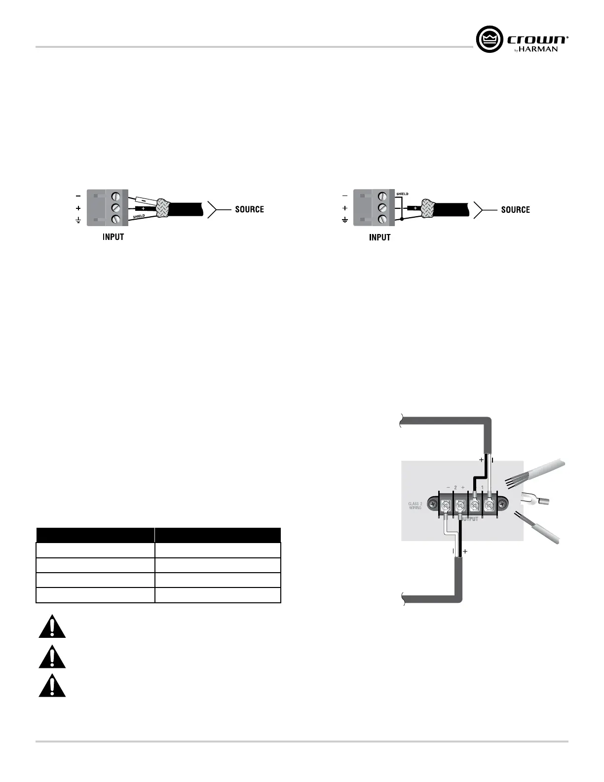
Figure 4 shows connector pin assignments for balanced wiring and Figure 5 shows connector pin assignments for unbalanced wiring. Note that for
bridge mono operation, only the odd-numbered input channels (1,3) should be wired for each bridged pair.
Figure 4: Balanced wiring Figure 5: Unbalanced wiring
Wiring Output Connectors
IMPORTANT: The amplifier output mode (Low Z, 70V, 100V) must be properly configured for the application before connecting the speakers. By default,
all outputs are configured for Low Z operation. See "Conguring the Amp" on page 11 for more information.
Before making any output connections, ensure the power cord is disconnected from the amplifier and carefully review the total impedance for loudspeakers
connected to each amplifier output. If multiple loudspeakers are connected to an output in Low Z mode (i.e., in series, parallel, or series-parallel), be certain
the total system impedance is within allowed specification for the output. When multiple loudspeakers are connected to one output in High Z mode, be
certain total tapped power is below the rated power output for the channel. See "Specications" on page 78 for supported load specifications.
NOTE: The Crown-designed output cover does not need to be removed to connect the output wiring.
Crown recommends using the included terminal fork connectors and two-conductor or four-
conductor, heavy gauge speaker wire. You may use terminal forks up to 10 AWG or bare wire
for your output connectors (see Figure 6). For best results, Crown recommends Panduit part
#PV10-6LF-L or equivalent terminal fork. For bare wire, it is highly recommended that output
wiring is tinned. To reduce strain on input and output wiring, Crown recommends the use of
horizontal lacer bars. For best results, Crown recommends Middle Atlantic
®
part# LBP-4R90
or equivalent horizontal lacer bar.
For low-impedance loads, refer to the table below and select the appropriate size of wire based
on the distance from amplifier to speaker.
Distance Wire Size
Up to 25 ft. (7.6m) 16 AWG
26-40 ft. (7.9-12.2m) 14 AWG
41-60 ft. (12.5-18.3m) 12 AWG
> 60 ft (18.3m) 10 AWG
CAUTION: Never use shielded cable for output wiring.
CAUTION: Never connect the speaker return to the chassis of the amplifier, or damage to the amplifier may result.
NOTE: Custom wiring should only be performed by qualified personnel. Class 2 output wiring is required.
For application-specific output connection diagrams, including how to wire outputs for bridge mono operation, see "Application Examples" on page
55
.
Figure 6: Wiring output connectors
 Loading...