Page 55
CDi DriveCore Series Operation Manual
Application Examples
Application Examples
Dual Mode, Low Z (2Ω, 4Ω, 8Ω, or 16Ω)
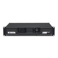
Audio Architect software settings are shown in Figure 66. Typical input/
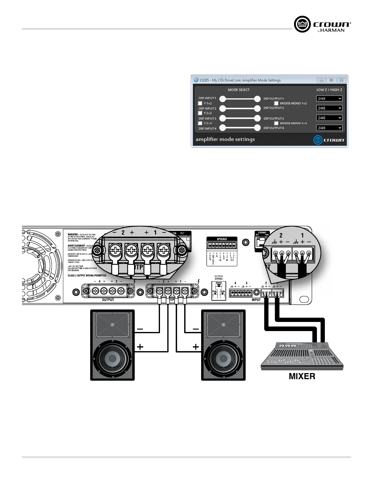
output wiring is shown in Figure 67.
INPUTS: Connect the input wires for each channel. See
"Wiring Input
Connectors" on page 7
for further information on analog input
wiring.
If the same input signal is to drive multiple outputs, the input signal
can be "Y'ed" by checking the "Y" checkboxes (see Figure 66). See
"Conguring Amp Wiring & Bridge Mode" on page 13 for
more information.
If using the BLU link input, it is important to understand that BLU link
is a digital audio bus and cannot be routed through an Ethernet switch
or router. Category 5e or higher cabling must be used for all BLU link
connections. To use the built-in BLU link fault protection, the BLU
link output of the last device on the bus must be connected back to the BLU link input of the first device. For additional information on making BLU link
connections and using BLU link, see
"Using BLU link" on page 59.
OUTPUTS: Maintain proper polarity (+/–) on output connectors. Connect the Channel 1 speaker’s positive (+) lead to amplifier Channel 1 positive
terminal; repeat for the negative (–) lead. Repeat Channel 2 wiring as for Channel 1, and for any subsequent channel pairs on multichannel models. See
"Wiring Output Connectors" on page 7 for additional information on output wiring.
2 1
Figure 67: System wiring in Dual mode
NOTE: Always route the input and output wires in separate bundles.
WARNING: Only connect to networks that remain inside the building.
Figure 66: Audio Architect amplifier mode settings
 Loading...