Page 36
CDi DriveCore Series Operation Manual
Using HiQnet Audio Architect
Configuring Inputs & Outputs in Audio Architect
Assigning Input Sources in Audio Architect
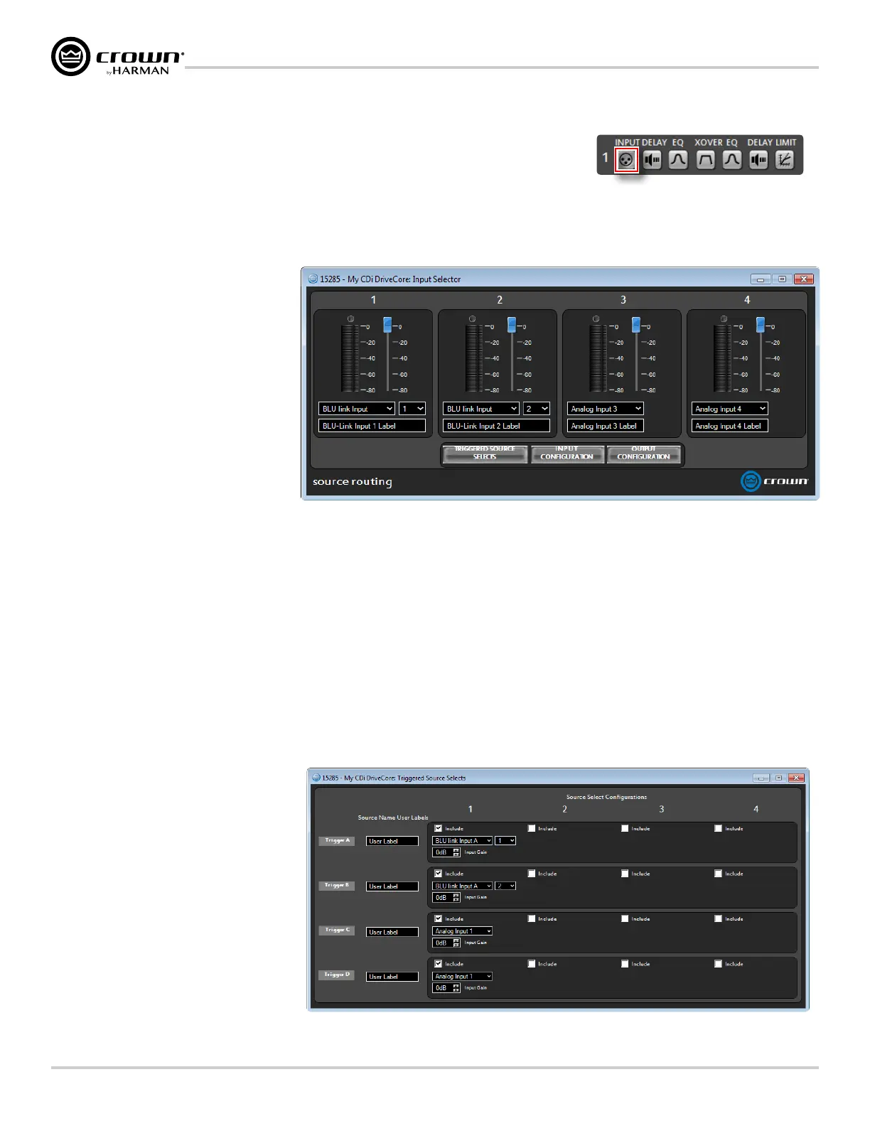
All channels of the CDi DriveCore signal processing share a single Input Selector panel (shown in
Figure 38). From this panel, you can select the audio signal that will be routed to each amplifier
channel and adjust the levels entering each channel's DSP chain.
The Input Selector panel can be accessed by clicking any of the INPUT buttons from the Main CDi DriveCore Control panel (see Figure 37).
1� Levels, Meters, & Clip Indicators
The level faders are used to adjust
signal levels entering the DSP chains
from the various input sources. The
meters in this panel display both peak
and RMS levels — the wider left meter
shows RMS level and the right meter
shows peak level for each channel. The
clip indicators light to indicate clipping
at the signal point just before the
loudspeaker management processing
(delays, EQ, crossover, etc.).
2� Input Selector Dropdown Menus
From these dropdown menus,
input channel assignments can be
selected for each channel. Analog
inputs are available for selection in
all CDi DriveCore amp models. Mono summed analog options are also available. Additional BLU link channel options are available in BLU link
CDi DriveCore amp models. When assigning BLU link channels, a second dropdown menu will appear, where the desired BLU link channel can be
selected, as shown in Figure 38. These BLU link channel assignment dropdown menus provide an easier method for assigning BLU link channels,
however, note that BLU link channels can also be assigned from the BLU link Input Channel Assignment window (see Figure 41).
3� Input Labels
These fields allow user-defined names to be entered for the analog input channels, which can be used for reference and added to custom control
panels.
4� Input Configuration and Output Configuration Buttons
Clicking the Input Configuration button opens the Input Configuration panel, where input levels and analog gain structure can be adjusted (see
"Conguring Inputs" on page 37 for more information). Clicking the Output Configuration button (available only in BLU link amp models)
opens the BLU link Output Configuration panel, where the amplifier's BLU link output channels can be configured (see "Conguring BLU link
Outputs" on page 38
for more information).
5� Triggered Source Selects Button
Pressing this button will open the
Triggered Source Selects panel (see
Figure 39). This panel makes it easier
to program a BSS Contrio Ethernet wall
controller to recall up to four source
selection states (Trigger A-D), along
with input gain settings and on-screen
controller labels. See "Programming
BSS Contrio Ethernet Wall
Controllers" on page 49
for
more information on using this panel
and configuring Contrio wall controllers.
Figure 37: Input button
Figure 38: Input Selector panel (BLU link CDi DriveCore model shown)
Figure 39: Triggered Source Selects panel
 Loading...