- 11 -
Wiring Diagrams
1) Connection of power supply
input terminal
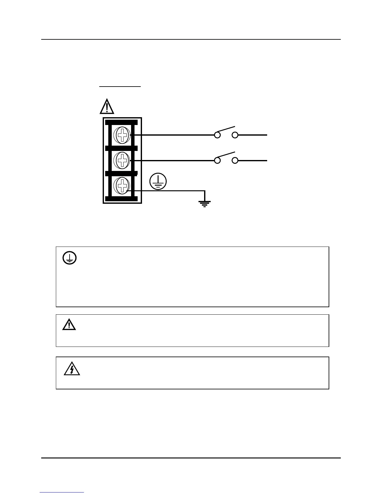
Fig. 2.7.1 Mains Power Supply
PROTECTIVE BONDING (grounding) of this controller and the enclosure in which it is
installed shall be in accordance with National and local electrical codes. To minimize
electrical noise and transients that may adversely affect the system, supplementary bonding
of the controller enclosure to a local ground, using a No.12(4 mm
2
) copper conductor, is
recommended.
CAUTION
To prevent product damage and failure, do not connect power supply cable to PE
terminal.
WARNING
Make sure that wiring to the main power supply is disconnected from the site AC source
before installing wiring.
100~240VAC
50~60Hz
Earth Ground
L1(H)
L2(N)
Neutral
Hot
AC Line
Voltage
 Loading...