- 63 -
3.14 PID ZONE SET screen
IPC5000 can have 8 different sets of PID constants based different setpoint or Process
variable ranges.
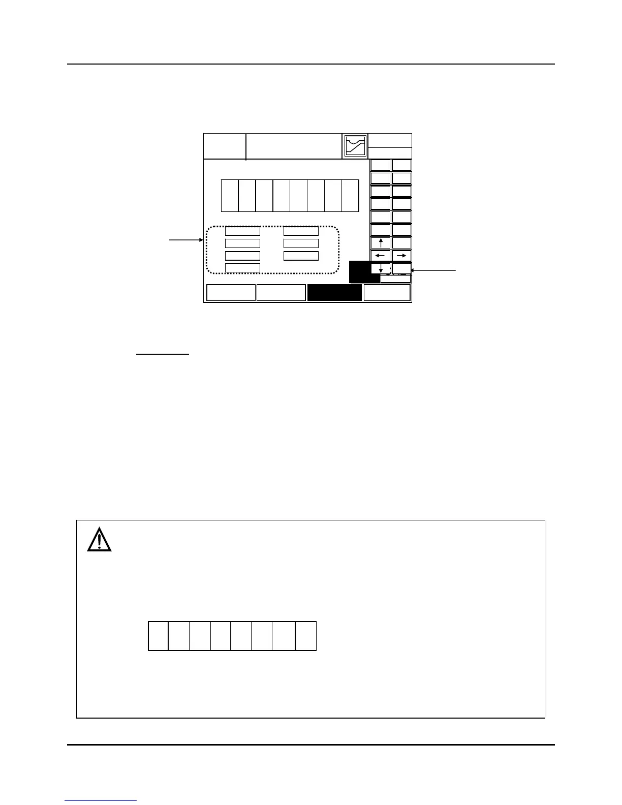
Fig. 3.14.1 PID ZONE SET screen
Change is forbidden under the ‘RUN’ operation.
(1) ZONE range configuration display & input
z ZONE configuration can be divided from 1 to 8
z Selection number is set up to the part typed in according to order.
z Magnitude of input value: T1< T2< T3< T4< T5< T6<T7
z Input range: LSPL to USPL ([RANGE SET\PV=])
(2) Channel selecting Button
z This button changes current Channel selection to the next Channel.
z When pressed, the button is highlighted.
z This button does not appear in [SETUP/CONTROL SET/Control mode = Single mode].
Screens set up by zone
1) The maximum of 8 zones:
When 8 zones are required, you may split into 1-8 zones in accordance with T1, T2, T3, T4,
T5, T6, and T7 set-up.
Set up values at T1, T2, T3, T4, T5,
T6, and T7 and split into 8 zones.
SP or PV → high
2 3 4 5 61
T1
T3
T4
T5
T2
78
T6
T7
2003.01.23
PID ZONE
EXIT
12H 59M
-80
T1
1 2 3456 78
-50
T1= T2=
0 50
T3= T4=
CH2CH1
100 250
T5= T6=
PID SET
PID ZONE
CONTROLPID VAL
400
T7= RANGE:-100.0 to 500.0
T2
T3
T4
T5
T6
T7
(1)
(2)
ESC
―
0
1
2 3
4 5
6 7
8 9
.
ENT
 Loading...