- 53 -
3.11 MODE Event set screen
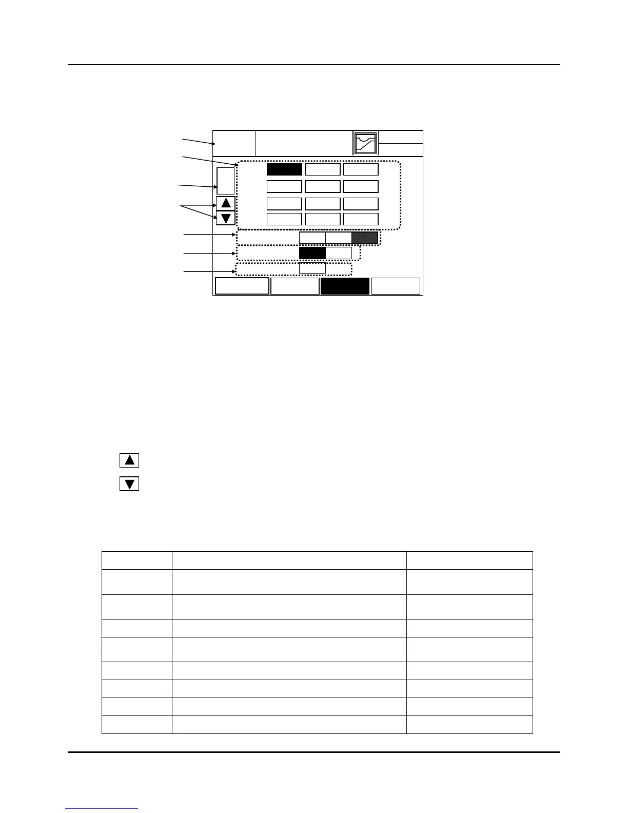
Fig. 3.11.1 MODE EVENT SET
(1) EVENT No. Display and Input
z EVENT No. for setup(21 ~ 40)
z The EVENT No. display to be set and buttons for input take place on the left. After this
button is pressed, use the keypad on the right pressing the ‘ENT’ key after the input
changes the value and it’s saved, pressing ‘ESC’ key cancels the process.
(2) Changing EVENT No. for setup.
(3) EVENT Content Display
z Highlighted according to ‘EVENT No’ configuration in (1) (See below Table).
Table 3.11.1 Mode Event information
ITEM Description Remarks
STOP When Program STOP(Quit), ON
READY, END, BREAK,
TROUBLE = ON
RUN During RUN operating, ON
HOLD, TUNE, WAIT =
ON
READY READY before operating the program, ON
END
When Program or Fix timer is completed and
the state is END, ON
TRBL When Trouble status occur, ON
HOLD When HOLD in process, ON
WAIT When the state us WAIT, ON
TUNE In Auto tuning, ON
41
2003.01.23
EXIT
12 H 59 M
MODE
No
MODE EVENT
CH1
SSIGN to
CONDITION
CH2
(3)
(2)
Return to Configuration
SET screen
(4)
(1)
MODE ASSIGN
3
OR AND
BOTH
STOP RUN READY
END TRBL HOLD
WAIT TUNE MAN
DOWN UP FIX
(5)
(6)
RANGE
OFFSET
MODE
ALARM
( + ) Increase : Whenever this button is pushed, the event No. increases by one.
( - ) Decrease : Whenever this button is pushed, the event No. decreases by one.
 Loading...