- 36 -
(a) IPC5000D (b) IPC5000S
Fig. 3.4.3 MV output selection combo box
The sources for PWM of IPC5000D are MV1, MV2, MV3 and MV4 and they mean the
outputs like below.
MV Description Addition Description
MV1 Heating control output for Loop(Channel) 1
Heating control output at Heat/Cool
Heating control output at normal PID
MV2 Heating control output for Loop(Channel) 1
Heating control output at Heat/Cool
Heating control output at normal PID
MV3 Cooling control output for Loop(Channel) 2 Cooling control output at Heat/Cool
MV4 Cooling control output for Loop(Channel) 2 Cooling control output at Heat/Cool
The sources for PWM of IPC5000D are MV1, MV2, MV3 and MV4 and they mean the
outputs like below.
MV Description Addition Description
MV1 Heating control output for Loop(Channel) 1
Heating control output at Heat/Cool
Heating control output at normal PID
MV2 Cooling control output for Loop(Channel) 2 Cooling control output at Heat/Cool
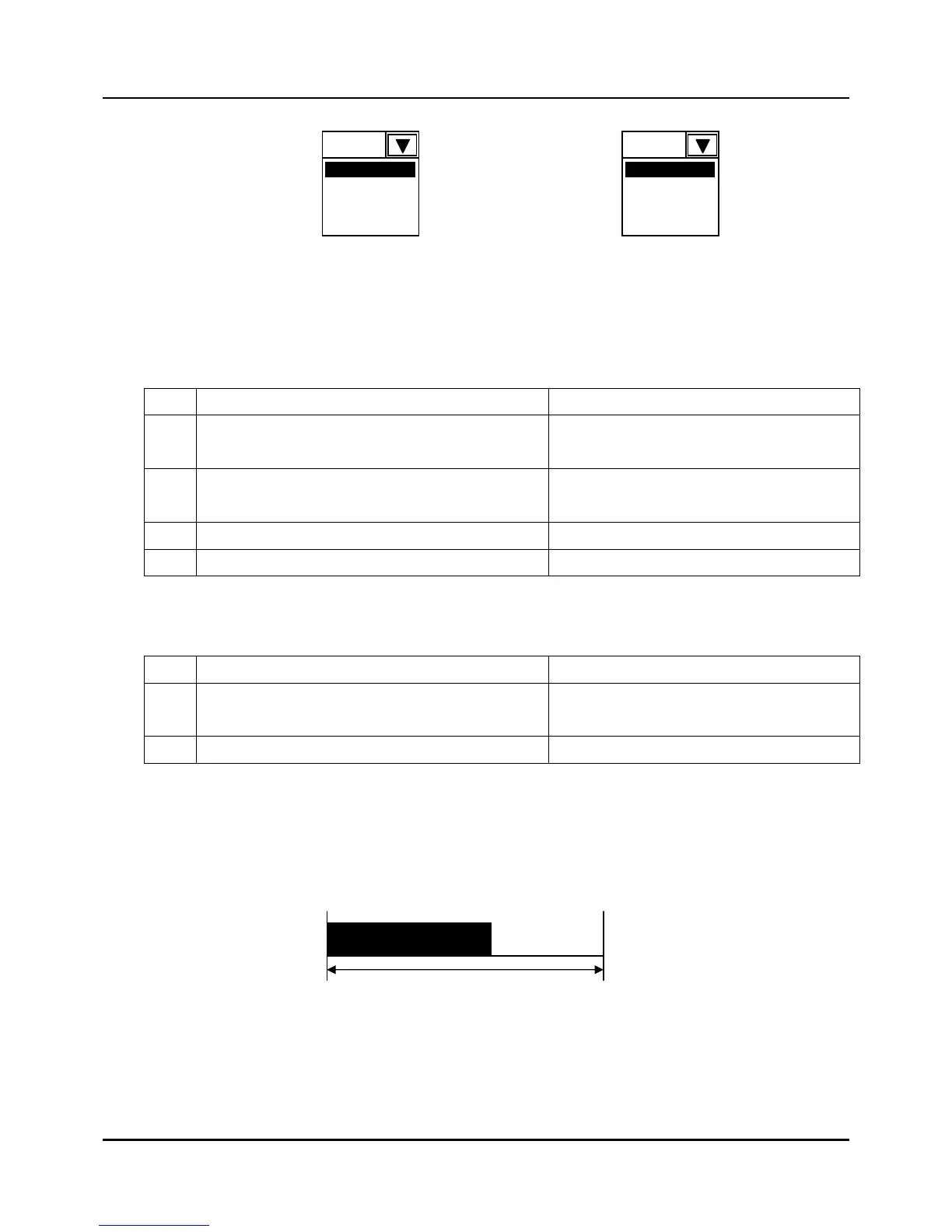
(3) Cycle time set: Sets the control cycle time for each pulse
z Set Range : 1 ~ 240 seconds
z The control cycle time set operates like fig 3.4.4.
Fig 3.4.4 Pulse control output at MV = 75%
MV1
MV1
MV2
MV3
MV4
Control cycle time(sec)
 Loading...