- 75 -
3.18 TROUBLE SET Screen
You can set the data related with the trouble messages and tune lock that are received
from the digital inputs.
The messages that you set in (1) and (2) in the Figure 3.18.1 will be displayed when the
ON signal is set for the trouble input, which enables you to identify the current trouble
status. Press the “CLEAR” button to clear the message.
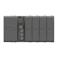
(a) IPC5000D
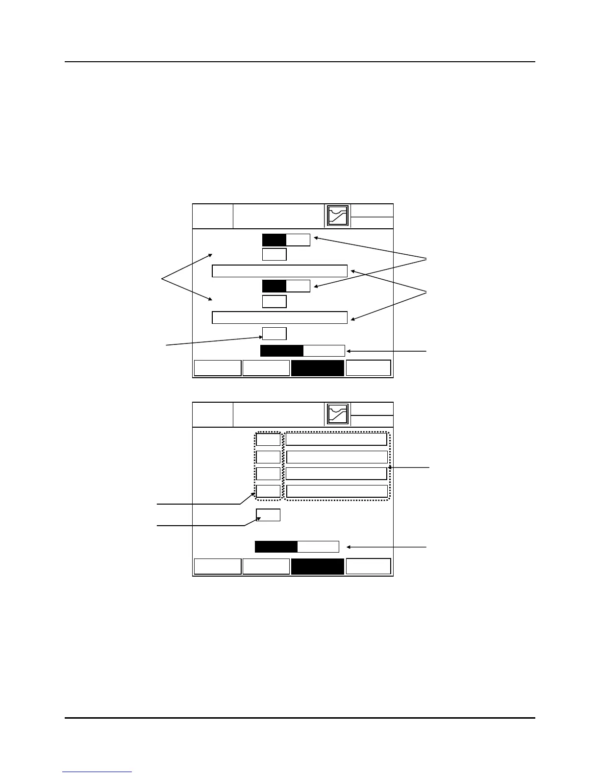
(b) IPC5000S
Fig. 3.18.1 Trouble and Tune Lock Setting Screen
(1) Button to Assign the channel : It is available for Asynchronous mode of IPC5000D.
Select the channel number to assign when trouble occur.
(2) Message number set button
Input the number that is displayed in the trouble input message list. When you input the
number displayed at the left side of the Figure 3.18.3, the message contents will be
(2)
(3)
(4)
(5)
03-02.WED
TROUBLE
EXIT
12.59.00
SYS SET
TROUBLE
INITIAL
NET SET
UNLOCK LOCK
 Loading...