- 12 -
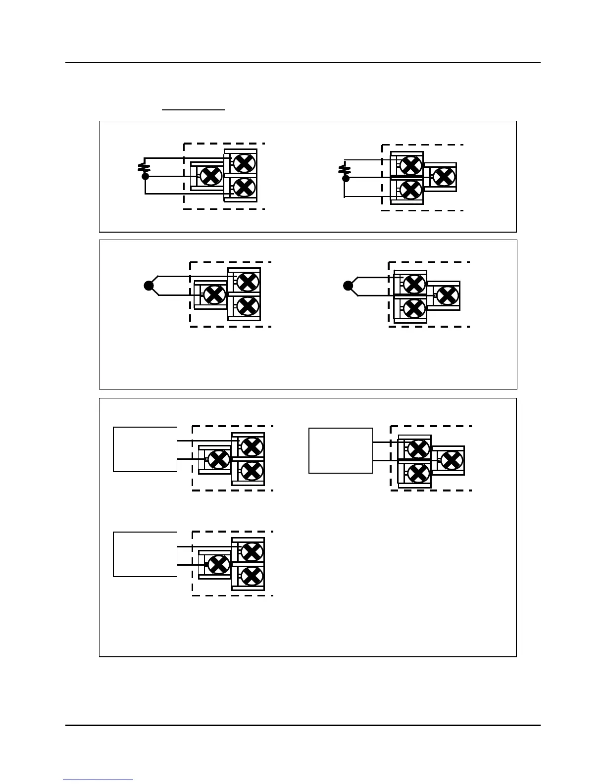
2) Connection of Analog input terminal
Fig. 2.7.2 Analog input 1 / input 2 Connections
For INPUT2 and INPUT3, these are NOT available for IPC5000S.
9
11
13
10
12
14
RTD (Resistance Temperature Detector) input
Input 1 Input 2
9
11
13
10
12
14
DC voltage or current input
Input 1 Input 2
Volt or
Milliampere
source
+
-
Volt or
Milliampere
source
-
+
15
16
Input 3
+
Volt or
Milliampere
source
-
* Be careful to connect the input polarities correctly.
9
11
13
10
12
14
Thermocouple input
Input 1 Input 2
+ +
-
-
* Be careful to connect the input polarities correctly.
 Loading...