- 16 -
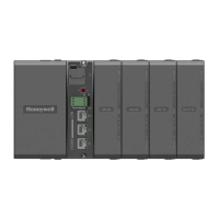
6) Connection of Auxiliary output (Option) – IPC5000D
Fig. 2.7.6 Auxiliary output 3 output 4 Connections
For Auxiliary output 3 and 4, these are NOT available for IPC5000S.
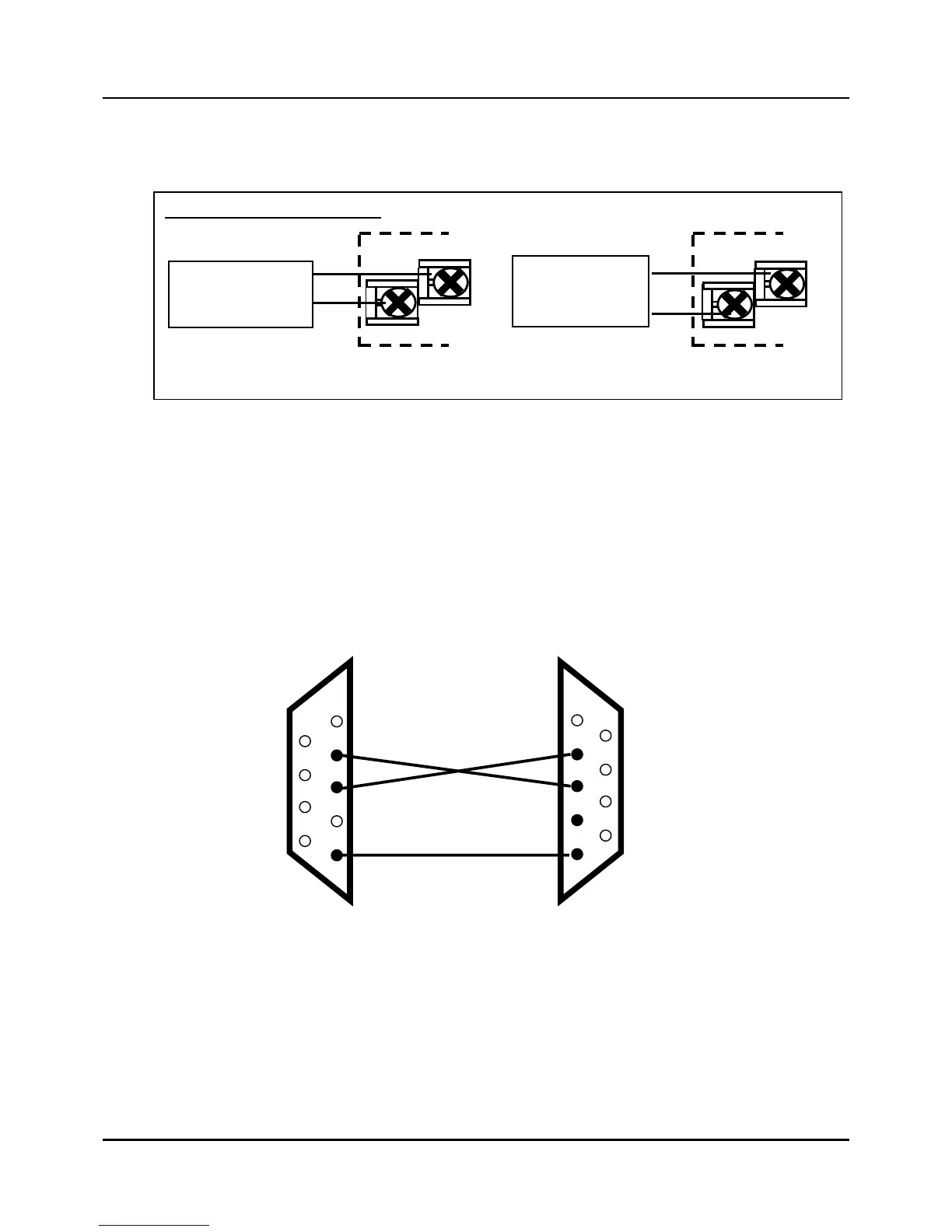
7) Connection of RS-232C communication
z 9 pin to 9 pin
Fig. 2.7.7 RS-232C communication 9 pin Connection
In this 3-wire cable, pin 2 and 3 should be crossed and pin 5 should be directly wired.
The length of the communication line between PC and IPC5000 should be 15m (49.2
ft.) or less.
Current outputs (4~20mA)
5
7
6
8
AUX. Output 3 AUX. Output 4
+
-
+
-
Load
(Max. 600Ω)
Load
(Max. 600Ω)
1
2
3
4
5
6
7
8
9
1
2
3
4
5
6
7
8
9
PC IPC5000
TXD TXD
RXD RXD
FG FG
 Loading...