- 23 -
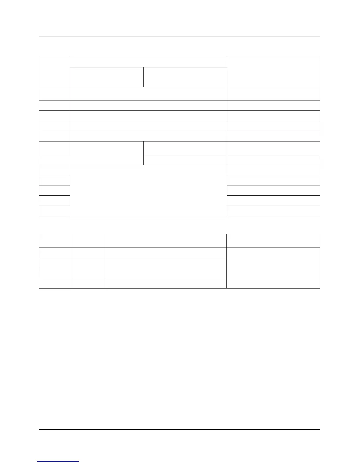
Table 2.7.3 The function table of External switch input (Digital input)
Function External
switch
number
IPC5000D IPC5000S
Detection way
SW1 RUN/STOP (RUN<-> STOP) Leading edge
SW2 HOLD ON status
SW3 ADV Leading edge
SW4 Trouble input 1
SW5 Trouble input 2
SW6 Trouble input 3 ON status
SW7
Channel selection
[NOTE 1]
Trouble input 4 ON status
SW8
SW9
SW10
SW11
SW12
Pattern selection
[NOTE 2]
[NOTE 1] Channel selection
SW6 SW7 Description Remark
ON ON Enabled both channel (CH1,CH2)
ON OFF Enabled CH1, but disabled CH2
OFF ON Enabled CH2, but disabled CH1
OFF OFF Disabled both channel (CH1,CH2)
These are available IPC5000D
 Loading...