ID3000/ID2000 Fire Panel Configuration Tool Manual
Introduction
1 - 4 997-291, Version 3.05
November 2010
1.4 Connecting a PC to the Panel
Use a suitable data communications cable. The
panel requires a male RS232 9-way D-type
connection from the cable. To connect the PC:
Caution: Direct connection of a PC to the panel’s
RS232 connector P1 will cause an earth
fault with potential damage to the PC.
Either use an isolated RS232 link or
(temporarily) disable the fault monitoring
circuit (steps 1 and 2 below). If an earth
fault already exists (LED next to link JP1
illuminated yellow), DO NOT connect
additional equipment likely to cause earth
faults as damage may result (i.e. inhibiting
the monitoring will not protect the
equipment).
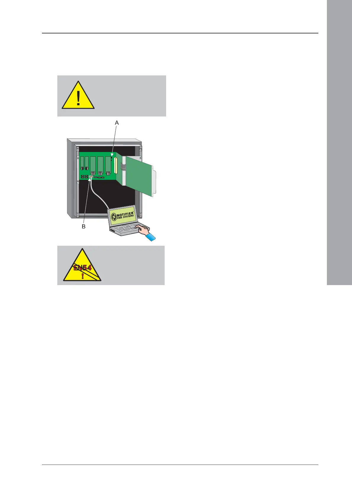
1 Disable the earth fault monitoring circuit by
removing the jumper link on JP1 (A) at the
top right-hand corner of the Base PCB. The
PCB is marked ‘EFD’ above the link.
2 Wait for at least one minute after disabling
the fault monitoring circuit, then use the data
communications cable to connect the PC
to the RS232 connector P1 (B) on the Base
PCB.
3 When the data transfer is complete (either
from panel to PC or PC to panel, see
Section 1.5.7), disconnect the PC from the
panel.
4 Enable the earth fault monitoring circuit by
replacing the jumper on JP1. To comply with
EN54-2: 8.2.4c, earth fault monitoring MUST
be enabled.
EN54-2: 8.2.4c
Earth Fault Monitoring
is required.
Incorrect connections could
result in damage to the
comms port of the PC. The
panel’s RS232 connector
P1 is NOT an isolated port.

 Loading...


